Section 18 Multi-Function Timer Pulse Unit (MTU)
Rev. 4.00 Sep. 14, 2005 Page 600 of 982
REJ09B0023-0400
Counter value
TGRC_3
update
TGRA_3
update
TGRA_3
TCNT_3
TCNT_4
Time
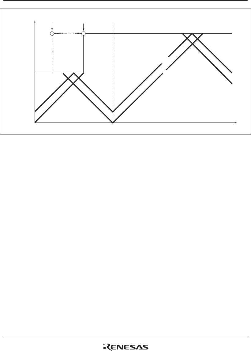
Figure 18.36 Example of PWM Cycle Updating
Register Data Updating: In complementary PWM mode, the buffer register is used to update the
data in a compare register. The update data can be written to the buffer register at any time. There
are five PWM duty and carrier cycle registers that have buffer registers and can be updated during
operation.
There is a temporary register between each of these registers and its buffer register. When
subcounter TCNTS is not counting, if buffer register data is updated, the temporary register value
is also rewritten. Transfer is not performed from buffer registers to temporary registers when
TCNTS is counting; in this case, the value written to a buffer register is transferred after TCNTS
halts.
The temporary register value is transferred to the compare register at the data update timing set
with bits MD3 to MD0 in the timer mode register (TMDR). Figure 18.37 shows an example of
data updating in complementary PWM mode. This example shows the mode in which data
updating is performed at both the counter crest and trough.
When rewriting buffer register data, a write to TGRD_4 must be performed at the end of the
update. Data transfer from the buffer registers to the temporary registers is performed
simultaneously for all five registers after the write to TGRD_4.
A write to TGRD_4 must be performed after writing data to the registers to be updated, even when
not updating all five registers, or when updating the TGRD_4 data. In this case, the data written to
TGRD_4 should be the same as the data prior to the write operation.


