Section 12 Bus State Controller (BSC)
Rev. 4.00 Sep. 14, 2005 Page 274 of 982
REJ09B0023-0400
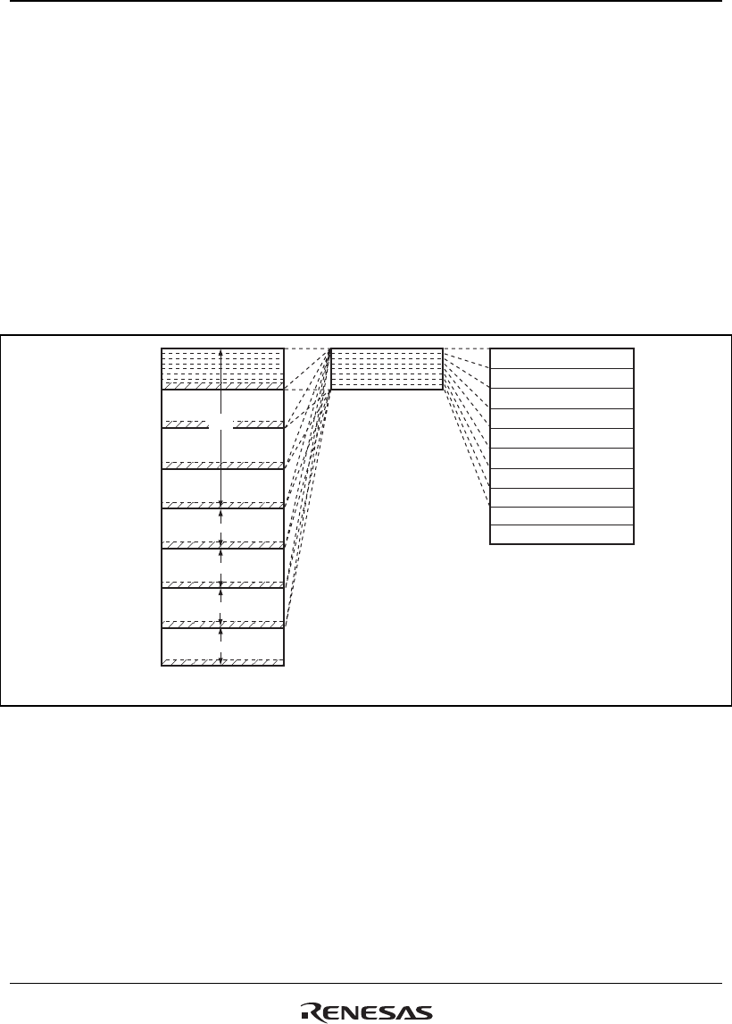
12.3.2 Shadow Area
Areas 0, 2 to 4, 5A, 5B, 6A, and 6B are decoded by addresses A28 to A26, which correspond to
areas 000 to 110. Address bits 31 to 29 are ignored. This means that the range of area 0 addresses,
for example, is H'00000000 to H'03FFFFFF, and its corresponding shadow space is the address
space between P0 and P3 obtained by adding to it H'20000000 × n (n = 1 to 6). The address range
for area 7 is H'1C000000 to H'1FFFFFFF. The address space H'1C000000 + H'20000000 × n–
H'1FFFFFFF + H'20000000 × n (n = 0 to 7) corresponding to the area 7 shadow space is reserved,
so do not use it.
Area P4 (H'E0000000 to H'EFFFFFFF) is an I/O area and is assigned for internal register
addresses.
Area 0 (CS0)
H'00000000
H'20000000
H'40000000
H'60000000
H'80000000
H'A0000000
H'C0000000
H'E0000000
Area 1 (Internal I/O)
Area 2 (CS2)
Area 3 (CS3)
Area 4 (CS4)
Area 5A (CS5A)
Area 6A (CS6A)
Area 7 (Reserved)
Address spacesby A28 to A0
Address Spaces by A31 to A0
P0
P1
P2
P3
P4
Area 5B (CS5B)
Area 6B (CS6B)
Figure 12.2 Address Space
