


Section 21 A/D Converter
Rev. 4.00 Sep. 14, 2005 Page 805 of 982
REJ09B0023-0400
21.3 Operation
The A/D converter operates by successive approximations with 10-bit resolution. It has three
operating modes: single mode, multi mode, and scan mode.
21.3.1 Single Mode
Single mode should be selected when only one A/D conversion on one channel is required. A/D
conversion starts when the ADST bit is set to 1 by software. The ADST bit remains set to 1 during
A/D conversion and is automatically cleared to 0 when conversion ends.
When conversion ends the ADF bit is set to 1. If the ADIE bit is also set to 1, an ADI interrupt is
requested at this time. To clear the ADF flag to 0, first read ADF, then write 0 to ADF.
When the mode or analog input channel must be switched during A/D conversion, to prevent
incorrect operation, first clear the ADST bit to 0 to halt A/D conversion. After making the
necessary changes, set the ADST bit to 1 to start A/D conversion again. The ADST bit can be set
at the same time as the mode or channel is changed.
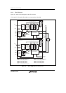
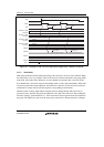
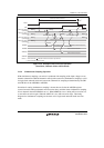
Typical operations when channel 1 (AN1) is selected in single mode are described next.
Figure 21.2 shows a timing diagram for this example.
1. Single mode is selected (MULTI = 0), input channel AN1 is selected (CH1 = 0, CH0 = 1), the
A/D interrupt is enabled (ADIE = 1), and A/D conversion is started (ADST = 1).
2. When A/D conversion is completed, the result is transferred into ADDRB0. At the same time
the ADF flag is set to 1, the ADST bit is cleared to 0, and the A/D converter becomes idle.
3. Since ADF = 1, ADIE = 1, and DMSL = 0 an ADI0 interrupt is requested.
4. The A/D interrupt handling routine starts.
5. The routine reads ADF, and then writes 0 to the ADF flag.
6. The routine reads and processes the conversion result (ADDRB0).
7. Execution of the A/D interrupts handling routine ends. Then, when the ADST bit is set to 1,
A/D conversion starts and steps 2 to 7 are executed.