Section 2 CPU
Rev. 4.00 Sep. 14, 2005 Page 42 of 982
REJ09B0023-0400
DSR is assigned as a system register and the following load/store instructions are provided:
STS DSR,Rn;
STS.L DSR,@-Rn;
LDS Rn,DSR;
LDS.L @Rn+,DSR;
When DSR is read by an STS instruction, the upper bits (bits 31 to 8) are all 0.
2.2 Data Formats
2.2.1 Register Data Format (Non-DSP Type)
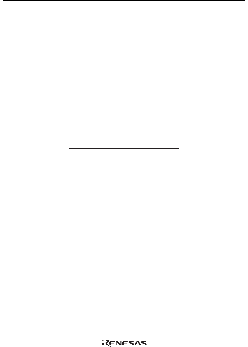
Register operands are always longwords (32 bits) (figure 2.9). When the memory operand is only
a byte (8 bits) or a word (16 bits), it is sign-extended into a longword when loaded into a register.
31 0
Longword
Figure 2.9 Longword Operand
2.2.2 DSP-Type Data Formats
This LSI has several different data formats that depend on the instruction. This section explains
the data formats for DSP type instructions.
Figure 2.10 shows three DSP-type data formats with different binary point positions. A CPU-type
data format with the binary point to the right of bit 0 is also shown for reference.
The DSP-type fixed point data format has the binary point between bit 31 and bit 30. The DSP-
type integer format has the binary point between bit 16 and bit 15. The DSP-type logical format
does not have a binary point. The valid data lengths of the data formats depend on the instruction
and the DSP register.


