


Section 2 CPU
Rev. 4.00 Sep. 14, 2005 Page 89 of 982
REJ09B0023-0400
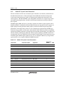
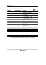
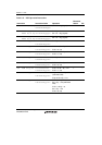
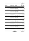
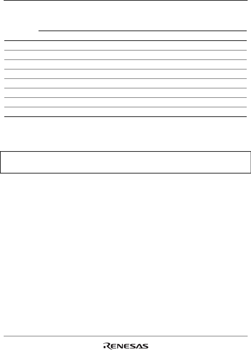
Table 2.30 Correspondence between DSP Instruction Operands and Registers
ALU/BPU Operations Multiply Operations
Register Sx Sy Dz Du Se Sf Dg
A0 Yes — Yes Yes — — Yes
A1 Yes — Yes Yes Yes Yes Yes
M0 — Yes Yes — — — Yes
M1 — Yes Yes — — — Yes
X0 Yes — Yes Yes Yes Yes —
X1 Yes — Yes — Yes — —
Y0 — Yes Yes Yes Yes Yes —
Y1 — Yes Yes — — Yes —
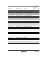
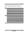
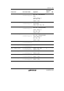
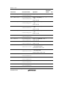
When writing parallel instructions, the B-field instruction is written first, followed by the A-field
instruction. A sample parallel processing program is shown in figure 2.16.
DCF
PADD A0, M0, A0 PMULS X0, Y0, M0 MOVX.W @R4+, X0 MOVY.W @R6+, Y0 [;]
PINC X1, A1 MOVX.W A0, @R5+R8 MOVY.W @R7+, Y0 [;]
PCMP X1, M0 MOVX.W @R4 [NOPY] [;]
Figure 2.16 Sample Parallel Instruction Program
Square brackets mean that the contents can be omitted.
The no operation instructions NOPX and NOPY can be omitted. Table 2.31 gives an overview of
the B field in parallel operation instructions.
A semicolon is the instruction line delimiter, but this can also be omitted. If the semicolon
delimiter is used, the area to the right of the semicolon can be used as a comment field. This has
the same function as with conventional SH tools.
The DSR register condition code bit (DC) is always updated on the basis of the result of an
unconditional ALU or shift operation instruction. Conditional instructions do not update the DC
bit. Multiply instructions, also, do not update the DC bit. DC bit updating is performed by means
of bits CS0 to CS2 in the DSR register. The DC bit update rules are shown in table 2.32.