Section 18 Multi-Function Timer Pulse Unit (MTU)
Rev. 4.00 Sep. 14, 2005 Page 638 of 982
REJ09B0023-0400
18.7.15 Overflow Flags in Reset Sync PWM Mode
When set to reset sync PWM mode, TCNT_3 and TCNT_4 start counting when the CST3 bit of
TSTR is set to 1. At this point, TCNT_4's count clock source and count edge obey the TCR_3
setting.
In reset sync PWM mode, with cycle register TGRA_3's set value at H'FFFF, when specifying
TGR3A compare-match for the counter clear source, TCNT_3 and TCNT_4 count up to H'FFFF,
then a compare-match occurs with TGRA_3, and TCNT_3 and TCNT_4 are both cleared. At this
point, TSR's overflow flag TCFV bit is not set.
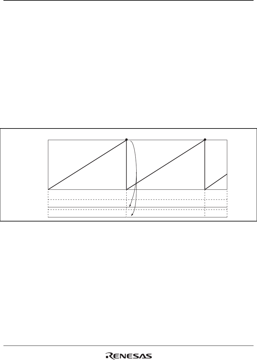
Figure 18.82 shows a TCFV bit operation example in reset sync PWM mode with a set value for
cycle register TGRA_3 of H'FFFF, when a TGRA_3 compare-match has been specified without
synchronous setting for the counter clear source.
TGRA_3
(H'FFFF)
H'0000
TCFV_3
TCFV_4
Counter cleared by compare match 3A
Not set
Not set
TCNT_3 = TCNT_4
Figure 18.82 Reset Sync PWM Mode Overflow Flag
18.7.16 Conflict between Overflow/Underflow and Counter Clearing
If overflow/underflow and counter clearing occur simultaneously, the TCFV/TCFU flag in TSR is
not set and TCNT clearing takes precedence.
Figure 18.83 shows the operation timing when a TGR compare match is specified as the clearing
source, and when H'FFFF is set in TGR.


