


Section 6 Power-Down Modes
Rev. 4.00 Sep. 14, 2005 Page 173 of 982
REJ09B0023-0400
2. Canceling Standby Mode
Standby mode is canceled by interrupts (NMI, IRQ) or a reset.
• Canceling with an Interrupt
The on-chip WDT can be used for hot starts. When an interrupt request is detected at the rising
or falling edge of NMI or IRQ, the clock will be supplied to the entire chip and standby mode
canceled after the time set in the WDT's timer control/status register has elapsed. The
STATUS1 and STATUS0 pins go low. Interrupt handling then begins and a code indicating
the interrupt source is set in the INTEVT2 registers. After the branch to the interrupt handling
routine, clear the STBY bit in the STBCR register. WDT stops automatically. If the STBY bit
is not cleared, WDT continues operation and a transition is made to standby mode* when the
WTCNT reaches H'80. A manual reset will not be accepted while the STBY bit is set.
Interrupts are accepted in standby mode even when the BL bit in the SR register is 1. If
necessary, save SPC and SSR to the stack before executing the SLEEP instruction.
Immediately after an interrupt is detected and until the system is taken out of standby mode,
the phase of the clock outputs from the CKIO and CKIO2 pins may be unstable.
Notes: * This standby mode can be canceled only by a power-on reset.
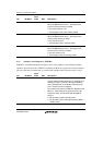
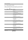
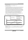
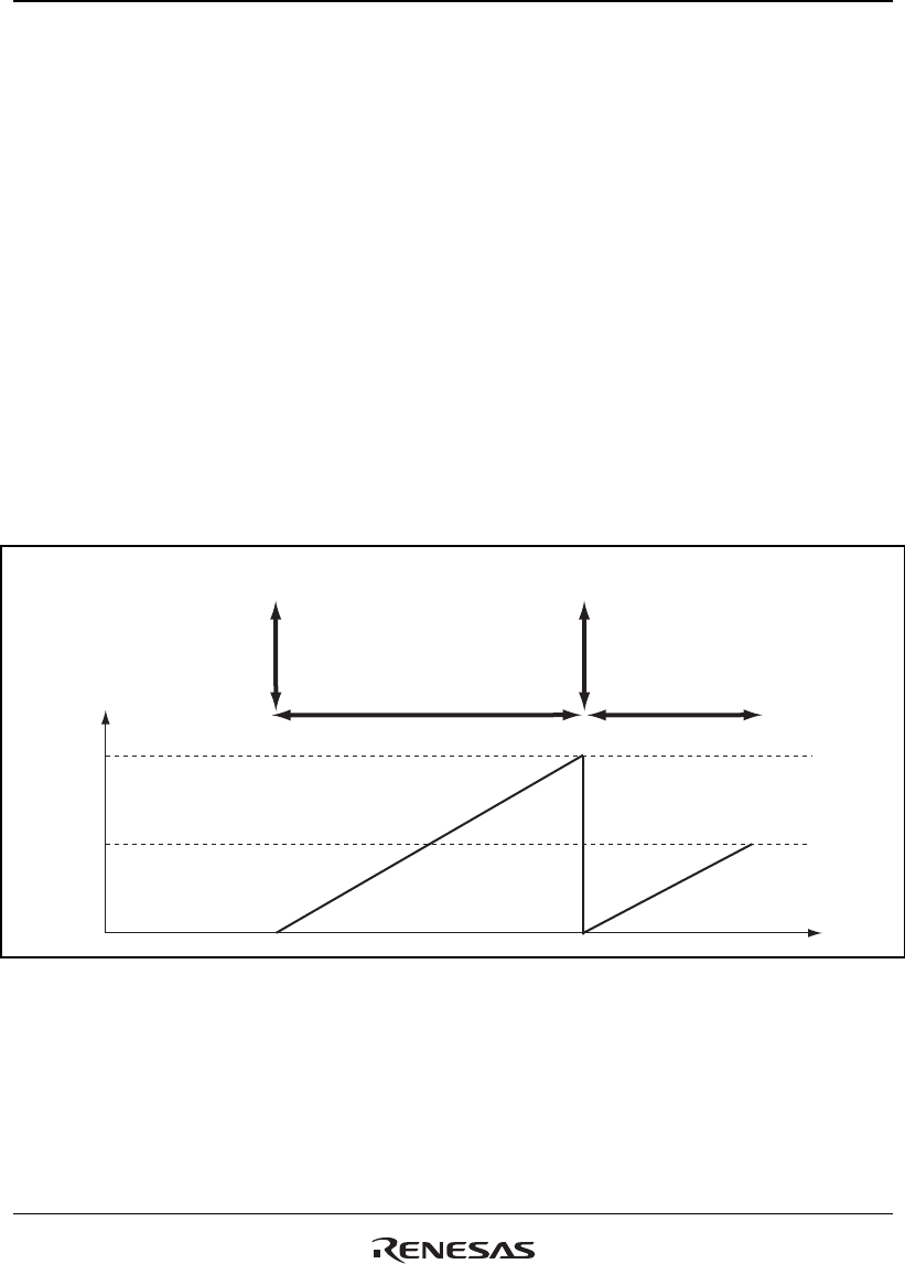
WTCNT value
H'FF
H'80
Time
Interrupt
request
WDT overflow and branch to
interrupt handling routine
Crystal oscillator settling
time and PLL synchronization
time
Clear bit STBCR.STBY before
WTCNT reaches H'80. When
STBCR. STBY is cleared, WTCNT
halts automatically.
Figure 6.1 Canceling Standby Mode with STBCR.STBY
• Canceling with a Reset
Standby mode is canceled by a reset using the RESETP or RESETM pin. Keep the RESETP or
RESETM pin low until the clock oscillation settles. The internal clock will continue to be
output to the CKIO pin.