Section 18 Multi-Function Timer Pulse Unit (MTU)
Rev. 4.00 Sep. 14, 2005 Page 597 of 982
REJ09B0023-0400
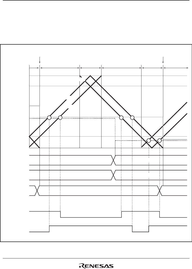
with the counter. In this interval, therefore, there are two compare match registers for one-phase
output, with the compare register containing the pre-change data, and the temporary register
containing the new data. In this interval, the three counters−TCNT_3, TCNT_4, and TCNTS−and
two registers−compare register and temporary register−are compared, and PWM output controlled
accordingly.
TGRA_3
TCDR
TGRA_4
TGRC_4
TDDR
H'0000
Buffer register
TGRC_4
Temporary register
TEMP2
Compare register
TGRA_4
Output waveform
Output waveform
Tb2 Ta Tb1 Ta Tb2 Ta
TCNT_3
TCNT_4
TCNTS
(Output waveform is active-low)
H'6400 H'0080
H'6400
H'6400
H'0080
H'0080
Transfer from temporary
register to compare register
Transfer from temporary
register to compare register
Figure 18.35 Example of Complementary PWM Mode Operation


