


Section 13 Direct Memory Access Controller (DMAC)
Rev. 4.00 Sep. 14, 2005 Page 440 of 982
REJ09B0023-0400
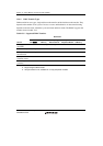
Bus Mode and Channel Priority Order: When channel 1 is transferring data in burst mode and a
request arrives for transfer on channel 0, which has higher-priority, the data transfer on channel 0
will begin immediately. In this case, if the transfer on channel 0 is also in burst mode, the transfer
on channel 1 will only resume on completion of the transfer on channel 0.
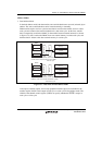
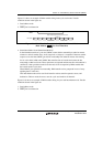
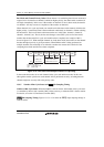
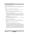
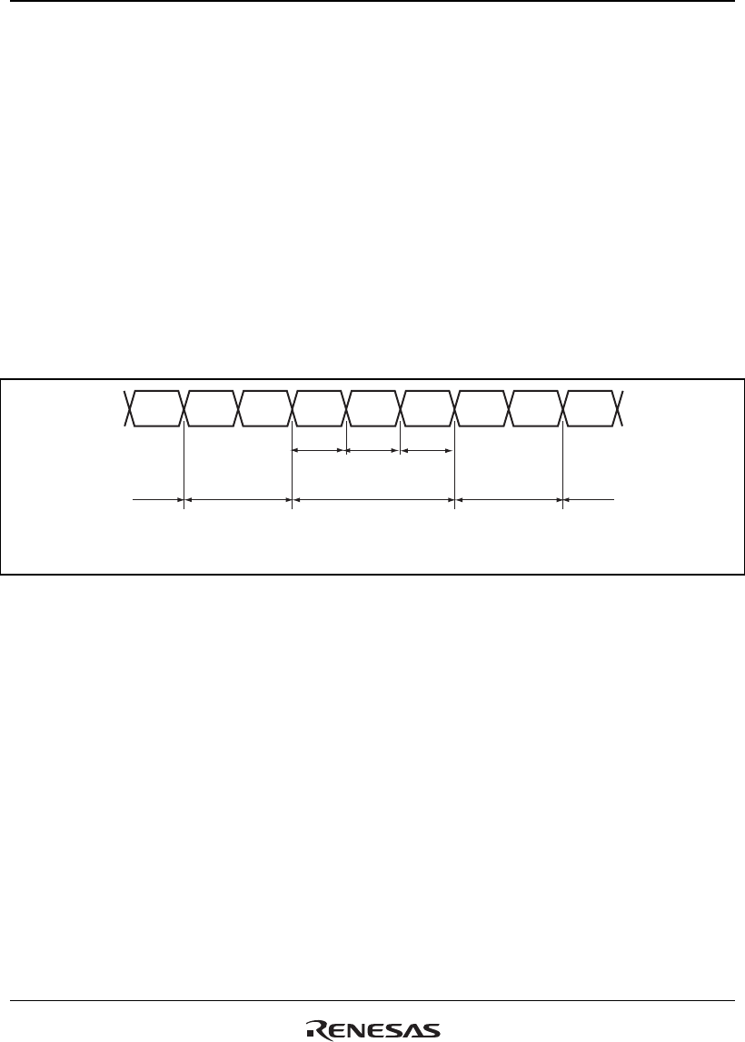
When channel 0 is in cycle steal mode, one transfer-unit of the data on this channel, which has the
higher priority, is transferred. Data is then transferred continuously on channel 1 without releasing
the internal bus. The bus will then switch between the two in this order: channel 1, channel 0,
channel 1, channel 0, etc. That is, the bus state changes so that CPU cycles are for burst-mode
transfer after the data transfer in cycle steal mode has been completed. An example of this is
shown in figure 13.12. When multiple channels are in the burst mode, data transfer on the channel
that has the highest priority is given precedence. When DMA transfer is being performed on
multiple channels, bus mastership is not released to another bus-master device until all of the
competing burst-mode transfers have been completed.
CPU
DMA
CH1
DMA
CH1
DMA
CH0
DMA
CH1
DMA
CH0
DMA
CH1
DMA
CH1
CPU
CH0 CH1 CH0
Cycle-steal mode in
DMAC CH0 and CH1
DMAC CH1
Burst mode
CPUCPU
Priority: CH0 > CH1
CH0: Cycle-steal mode
CH1: Burst mode
DMAC CH1
Burst mode
Figure 13.12 Bus State when Multiple Channels Are Operating
In the round-robin mode, do not mix channels in the cycle steal and burst modes. In this case,
although the transfer operation on each channel will be performed correctly, switching between
channels might not correctly follow the priority order.
13.4.5 Number of Bus Cycle States and DREQ Pin Sampling Timing
Number of Bus Cycle States: When the DMAC is the bus master, the number of bus cycle states
is controlled by the bus state controller (BSC) in the same way as when the CPU is the bus master.
For details, see section 12, Bus State Controller (BSC).
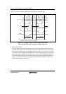
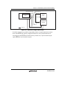
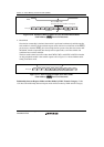
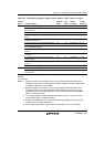
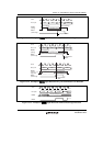
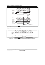
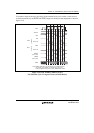
DREQ Pin Sampling Timing: Figures 13.13 to 13.16 show the DREQ input sampling timings in
each bus mode.