


Section 19 Serial Communication Interface with FIFO (SCIF)
Rev. 4.00 Sep. 14, 2005 Page 727 of 982
REJ09B0023-0400
• Transmitting Serial Data (Asynchronous Mode)
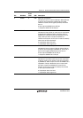
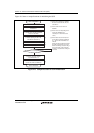
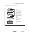
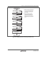
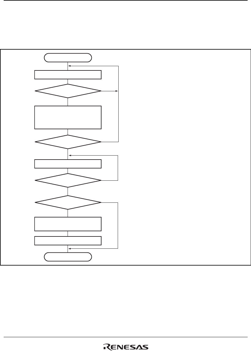
Figure 19.4 shows a sample flowchart for serial transmission.
Use the following procedure for serial data transmission after enabling the SCIF for transmission.
Start of transmission
Read TDFE flag in SCFSR
TDFE = 1?
Write transmit data in SCFTDR,
and read 1 from TDFE flag
and TEND flag in SCFSR,
then clear to 0
All data transmitted?
Read TEND flag in SCFSR
TEND = 1?
Break output?
Clear SPB2DT to 0 and
set SPB2IO to 1
Clear TE bit in SCSCR to 0
End of transmission
No
Yes
No
Yes
No
Yes
No
Yes
[1] SCIF status check and transmit data
write:
Read SCFSR and check that the
TDFE flag is set to 1, then write
transmit data to SCFTDR, and read 1
from the TDFE and TEND flags, then
clear to 0.
The number of transmit data bytes
that can be written is 16 - (transmit
trigger set number).
[2] Serial transmission continuation
procedure:
To continue serial transmission, read
1 from the TDFE flag to confirm that
writing is possible, then write data to
SCFTDR, and then clear the TDFE
flag to 0.
[3] Break output at the end of serial
transmission:
To output a break in serial
transmission, clear the SPB2DT bit to
0 and set the SPB2IO bit to 1 in
SCSPTR, then clear the TE bit in
SCSCR to 0.
In [1] and [2], it is possible to
ascertain the number of data bytes
that can be written from the number
of transmit data bytes in SCFTDR
indicated by the upper 8 bits of
SCFDR.
[1]
[2]
[3]
Figure 19.4 Sample Flowchart for Transmitting Serial Data