Section 18 Multi-Function Timer Pulse Unit (MTU)
Rev. 4.00 Sep. 14, 2005 Page 558 of 982
REJ09B0023-0400
Table 18.27 Output Level Select Function
Bit 1 Function
Compare Match Output
OLSP Initial Output Active Level
Increment Count Decrement Count
0 High level Low level Low level High level
1 Low level High level High level Low level
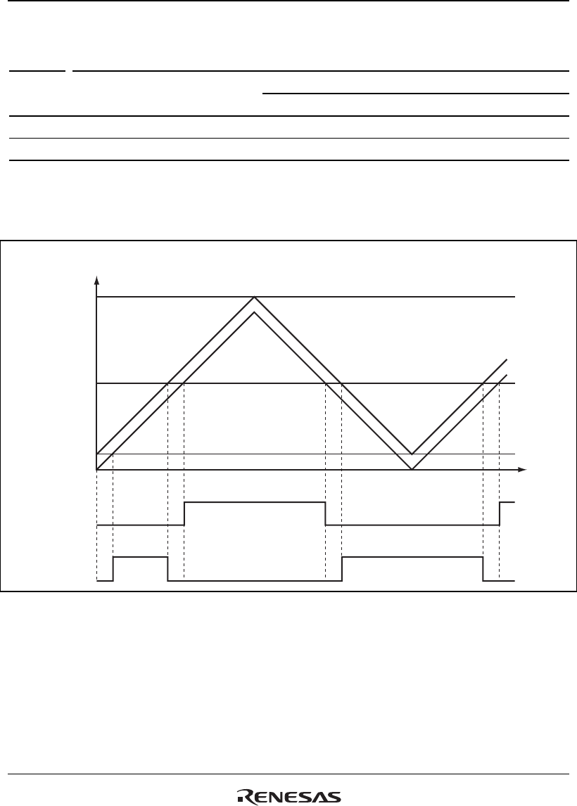
Figure 18.2 shows an example of complementary PWM mode output (one phase) when OLSN =
1, OLSP = 1.
TCNT_3, and
TCNT_4 values
TGRA_3
TGRA_4
TDDR
H'0000
Time
TCNT_4
TCNT_3
Positive
phase output
Reverse
phase output
Active level
Compare match
output (up count)
Initial
output
Initial
output
Active
level
Compare match
output (down count)
Compare match
output (down count)
Compare match
output (up count)
Active level
Figure 18.2 Complementary PWM Mode Output Level Example


