


Section 3 DSP Operation
Rev. 4.00 Sep. 14, 2005 Page 111 of 982
REJ09B0023-0400
Overflow Protection: The S bit in SR is also effective for arithmetic shift operation in the DSP
unit. See section 3.1.8, Overflow Protection, for details.
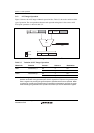
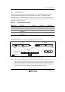
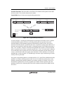
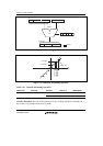
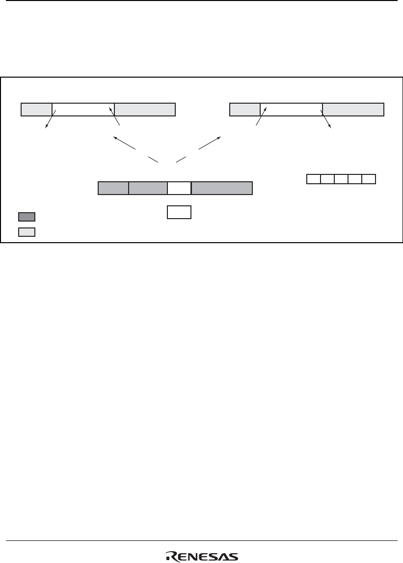
Logical Shift: Figure 3.10 shows the logical shift operation flow.
DSR
GT Z N V
DC
Updated
7g 0g 31 16 15 0
Sy
7g 0g 31 16 15 0
Shift outShift out
0
0
Cleared
Left Shift
Right Shift
7g 0g 31 22 21 16
Imm2
50
15 0
Shift amount data:
(Source 2)
> = 0 < 0
+16 to –16
Ignored
Figure 3.10 Logical Shift Operation Flow
As shown in figure 3.10, the logical shift operation uses the upper word of the source 1 operand
and the destination operand. The lower word and guard-bit parts are ignored for the source
operand and those of the destination operand are automatically cleared as in the ALU logical
operations. The shift amount is specified by the source 2 operand as an integer data. The source 2
operand can be specified by either the register or immediate operand. The available shift range is
from –16 to +16. Here, a negative value means the right shift, and a positive value means the left
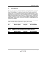
shift. It is possible for any source 2 operand to specify from –32 to +31, but the result is unknown
if an invalid shift value is specified. In case of a shift with an immediate operand instruction, the
source 1 operand must be the same register as the destination's. These operations are executed in
the DSP stage, as shown in figure 3.2. The DSP stage is the same stage as the MA stage in which
memory access is performed.
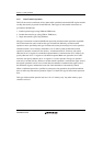
Every time a logical shift operation is executed, the DC, N, Z, V and GT bits in DSR are basically
updated in accordance with the operation result. In case of a conditional operation, they are not
updated even though the specified condition is true and the operation is executed. In case of an
unconditional operation, they are always updated in accordance with the operation result. The
definition of the DC bit is selected by the CS0 to CS2 (condition selection) bits in DSR. The DC
bit result is: