


Section 2 CPU
Rev. 4.00 Sep. 14, 2005 Page 41 of 982
REJ09B0023-0400
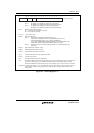
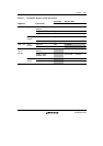
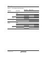
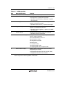
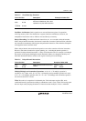
Table 2.4 DSR Register Bits
Bits Name (Abbreviation) Function
31 to 8 Reserved bits 0: Always read as 0; always use 0 as the write value
7 Signed Greater Than bit (GT) Indicates that the operation result is positive (except 0),
or that operand 1 is greater than operand 2
1: Operation result is positive, or operand 1 is greater
than operand 2
6 Zero bit (Z) Indicates that the operation result is zero (0), or that
operand 1 is equal to operand 2
1: Operation result is zero (0), or operands are equal
5 Negative bit (N) Indicates that the operation result is negative, or that
operand 1 is smaller than operand 2
1: Operation result is negative, or operand 1 is smaller
than operand 2
4 Overflow bit (V) Indicates that the operation result has overflowed
1: Operation result has overflowed
3 to 1 Condition Select bits (CS) Designate the mode for selecting the operation result
status to be set in the DC bit
Do not set these bits to 110 or 111
000: Carry/borrow mode
001: Negative value mode
010: Zero mode
011: Overflow mode
100: Signed greater mode
101: Signed greater than or equal to mode
0 DSP Condition bit (DC) Sets the status of the operation result in the mode
designated by the CS bits
0: Designated mode status has not occurred (false)
1: Designated mode status has occurred
Note: After execution of a PADDC/PSUBC instruction, the DC bit sets the status of the operation
result in carry/borrow mode regardless of the CS bits.