


Section 16 I
2
C Bus Interface 2 (IIC2)
Rev. 4.00 Sep. 14, 2005 Page 473 of 982
REJ09B0023-0400
Section 16 I
2
C Bus Interface 2 (IIC2)
The I
2
C bus interface 2 conforms to and provides a subset of the Philips I
2
C (Inter-IC) bus
interface functions. However, the configuration of the registers that control the I
2
C bus differs
partly from the Philips register configuration.
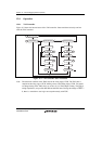
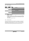
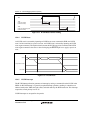
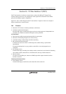
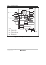
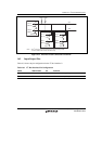
Figure 16.1 shows a block diagram of the I
2
C bus interface 2. Figure 16.2 shows an example of
I/O pin connections to external circuits.
16.1 Features
• Selection of I
2
C format or clocked synchronous serial format
• Continuous transmission/reception
Since the shift register, transmit data register, and receive data register are independent from
each other, the continuous transmission/reception can be performed.
I
2
C bus format:
• Start and stop conditions generated automatically in master mode
• Selection of acknowledge output levels when receiving
• Automatic loading of acknowledge bit when transmitting
• Bit synchronization/wait function
In master mode, the state of SCL is monitored per bit, and the timing is synchronized
automatically.
If transmission/reception is not yet possible, set the SCL to low until preparations are
completed.
• Six interrupt sources
Transmit data empty (including slave-address match), transmit end, receive data full (including
slave-address match), arbitration lost, NACK detection, and stop condition detection
• Direct bus drive
Two pins, SCL and SDA pins, function as NMOS open-drain outputs when the bus drive
function is selected.
Clocked synchronous format:
• Four interrupt sources
Transmit-data-empty, transmit-end, receive-data-full, and overrun error