


Section 21 A/D Converter
Rev. 4.00 Sep. 14, 2005 Page 806 of 982
REJ09B0023-0400
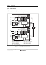
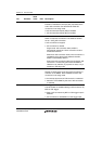
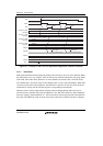
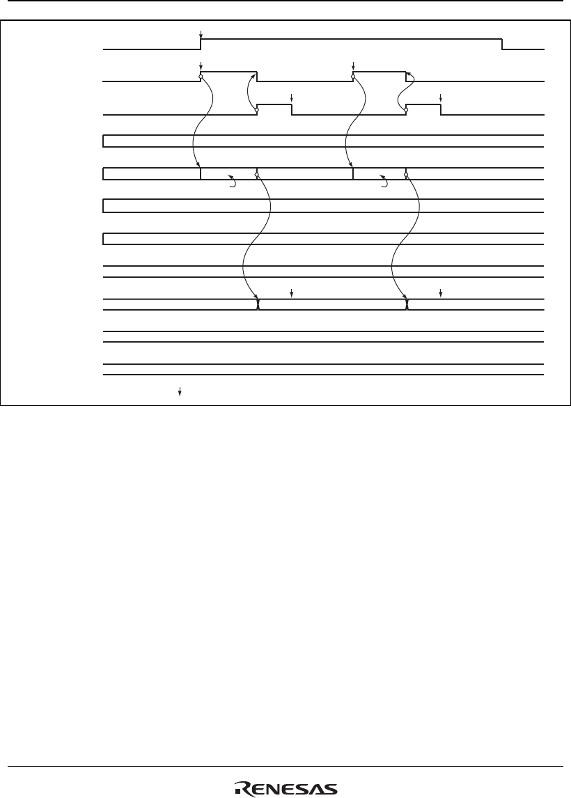
Channel 0 (AN0)
operating
ADIE
ADST
ADF
Channel 1 (AN1)
operating
Channel 2 (AN2)
operating
Channel 3 (AN3)
operating
ADDRA
ADDRB
ADDRC
ADDRD
Waiting
Waiting
Waiting
Waiting
Waiting Waiting
A/D conversion starts
Set*
Set* Set*
Clear* Clear*
A/D conversion result 1
A/D conversion result 2
Read result
Read result
A/D conversion 1 A/D conversion result 2
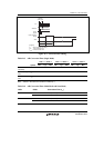
Note: * Vertical arrows ( ) indicate instruction execution by software.
Figure 21.2 Example of A/D Converter Operation (Single Mode, Channel 1 Selected)
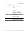
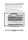
21.3.2 Multi Mode
Multi mode should be selected when performing A/D conversions on one or more channels. When
the ADST bit is set to 1 by software, A/D conversion starts on the first channel in the group (A/D0
when AN0, A/D1 when AN4). When two or more channels are selected, after conversion of the
first channel ends, conversion of the second channel (AN1 or AN5) starts immediately. When A/D
conversions end on the selected channels, the ADST bit is cleared to 0. The conversion results are
transferred for storage into the A/D data registers corresponding to the channels.
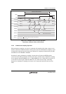
When the mode or analog input channel selection must be changed during A/D conversion, to
prevent incorrect operation, first clear the ADST bit to 0 to halt A/D conversion. After making the
necessary changes, set the ADST bit to 1. A/D conversion will start again from the first channel in
the group. The ADST bit can be set at the same time as the mode or channel selection is changed.