


Section 12 Bus State Controller (BSC)
Rev. 4.00 Sep. 14, 2005 Page 269 of 982
REJ09B0023-0400
Section 12 Bus State Controller (BSC)
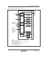
The bus state controller (BSC) outputs control signals for various types of memory that is
connected to the external address space and external devices. BSC functions enable this LSI to
connect directly with SRAM, SDRAM, and other memory storage devices, and external devices.
12.1 Features
The BSC has the following features:
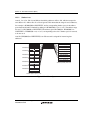
1. Physical address space is divided into eight areas
A maximum 32 or 64 Mbytes for each of the eight areas, CS0, CS2 to CS4, CS5A, CS5B,
CS6A and CS6B, totally 384 Mbytes.
A maximum 64 Mbytes for each of the six areas, CS0, CS2 to CS4, CS5, and CS6, totally a
total of 384 Mbytes.
Can specify the normal space interface, SRAM interface with byte selection, burst ROM
(clock synchronous or asynchronous), MPX-I/O, burst MPX-I/O, and SDRAM for each
address space.
Can select the data bus width (8, 16, or 32 bits) for each address space.
Controls the insertion of the wait state for each address space.
Controls the insertion of the wait state for each read access and write access.
Can set the independent idling cycle in the continuous access for five cases: read-write (in
same space/different space), read-read (in same space/different space), the first cycle is a
write access.
2. Normal space interface
Supports the interface that can directly connect to the SRAM.
3. Burst ROM interface (clock asynchronous)
High-speed access to the ROM that has the page mode function.
4. MPX-I/O interface
Can directly connect to a peripheral LSI that needs an address/data multiplexing.
5. SDRAM interface
Can set the SDRAM up to 2 areas.
Multiplex output for row address/column address.
Efficient access by single read/single write.
High-speed access by the bank-active mode.
Supports an auto-refresh and self-refresh.