Section 18 Multi-Function Timer Pulse Unit (MTU)
Rev. 4.00 Sep. 14, 2005 Page 529 of 982
REJ09B0023-0400
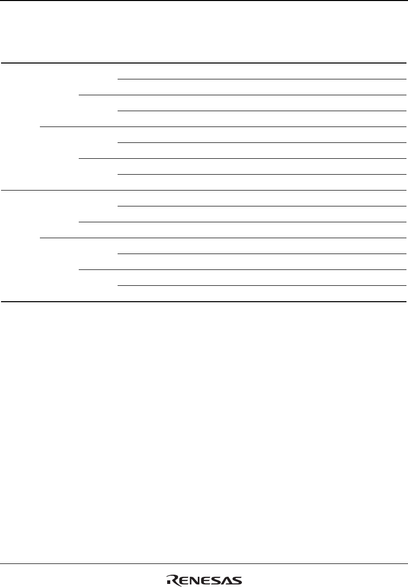
Table 18.9 MD0 to MD3
Bit 3
MD3
Bit 2
MD2
Bit 1
MD1
Bit 0
MD0
Description
0 0 0 0 Normal operation
1 Reserved (do not set)
1 0 PWM mode 1
1 PWM mode 2*
1
1 0 0 Phase counting mode 1*
2
1 Phase counting mode 2*
2
1 0 Phase counting mode 3*
2
1 Phase counting mode 4*
2
1 0 0 0 Reset synchronous PWM mode*
3
1 Reserved (do not set)
1 X Reserved (do not set)
1 0 0 Reserved (do not set)
1 Complementary PWM mode 1 (transmit at peak)*
3
1 0 Complementary PWM mode 2 (transmit at valley)*
3
1 Complementary PWM mode 2 (transmit at peak and valley)*
3
[Legend]
X: Don't care
Notes: 1. PWM mode 2 cannot be set for channels 3, 4.
2. Phase counting mode cannot be set for channels 0, 3, 4.
3. Reset synchronous PWM mode, complementary PWM mode can only be set for
channel 3. When channel 3 is set to reset synchronous PWM mode or complementary
PWM mode, the channel 4 settings become ineffective and automatically conform to the
channel 3 settings. However, do not set channel 4 to reset synchronous PWM mode or
complementary PWM mode. Reset synchronous PWM mode and complementary PWM
mode cannot be set for channels 0, 1, 2.


