


Section 18 Multi-Function Timer Pulse Unit (MTU)
Rev. 4.00 Sep. 14, 2005 Page 528 of 982
REJ09B0023-0400
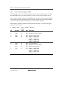
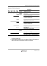
18.3.2 Timer Mode Register (TMDR)
The TMDR registers are 8-bit readable/writable registers that are used to set the operating mode of
each channel. The MTU has five TMDR registers, one for each channel. TMDR register settings
should be changed only when TCNT operation is stopped.
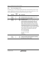
Bit Bit Name
Initial
value R/W Description
7, 6 All 1 Reserved
These bits are always read as 1. The write value should
always be 1.
5 BFB 0 R/W Buffer Operation B
Specifies whether TGRB is to operate in the normal
way, or TGRB and TGRD are to be used together for
buffer operation. When TGRD is used as a buffer
register, TGRD input capture/output compare is not
generated.
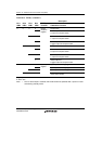
In channels 1 and 2, which have no TGRD, bit 5 is
reserved. It is always read as 0, and should only be
written with 0.
0: TGRB and TGRD operate normally
1: TGRB and TGRD used together for buffer operation
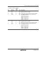
4 BFA 0 R/W Buffer Operation A
Specifies whether TGRA is to operate in the normal
way, or TGRA and TGRC are to be used together for
buffer operation. When TGRC is used as a buffer
register, TGRC input capture/output compare is not
generated.
In channels 1 and 2, which have no TGRC, bit 4 is
reserved. It is always read as 0, and should only be
written with 0.
0: TGRA and TGRD operate normally
1: TGRA and TGRC used together for buffer operation
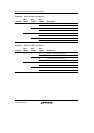
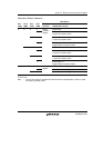
3
2
1
0
MD3
MD2
MD1
MD0
0
0
0
0
R/W
R/W
R/W
R/W
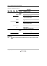
Modes 3 to 0
These bits are used to set the timer operating mode.
See table 18.9 for details.