


Section 3 DSP Operation
Rev. 4.00 Sep. 14, 2005 Page 112 of 982
REJ09B0023-0400
1. Carry or Borrow Mode: CS[2:0] = 000
The DC bit indicates the last shifted out data as the operation result.
2. Negative Value Mode: CS[2:0] = 001
Bit 31 of the operation result is loaded into the DC bit.
3. Zero Value Mode: CS[2:0] = 010
The DC bit is set when the operation result is zero; otherwise it is cleared.
4. Overflow Mode: CS[2:0] = 011
The DC bit is always cleared.
5. Signed Greater Than Mode: CS[2:0] = 100
The DC bit is always cleared.
6. Signed Greater Than or Equal Mode: CS[2:0] = 101
The DC bit is always cleared.
The N bit always indicates the same state as the DC bit set in negative value mode by the CS[2:0]
bits. See the negative value mode part above. The Z bit always indicates the same state as the DC
bit set in zero value mode by the CS[2:0] bits. See the zero value mode part above. The V bit
always indicates the same state as the DC bit set in overflow mode by the CS[2:0] bits, but it is
always cleared in this operation. So is the GT bit.
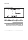
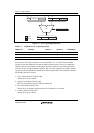
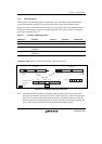
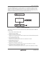
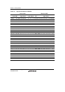
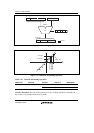
3.1.6 Most Significant Bit Detection Operation
The PDMSB, most significant bit detection operation, is used to calculate the shift amount for
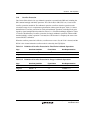
normalization. Figure 3.11 shows the PDMSB operation flow and table 3.8 shows the operation
definition. Table 3.9 shows the possible variations of this type of operation. The correspondence
between each operand and registers is the same as for ALU fixed-point operations, as shown in
table 3.2.
Note: The result of the MSB detection operation is basically 24 bits as well as ALU integer
operation, the upper 16 bits of the base precision and 8 bits of the guard-bit parts. When a
register not providing the guard-bit parts is specified as a destination operand, the upper
word of the operation result is input into the destination register.
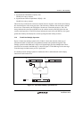
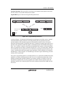
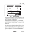
As shown in figure 3.11, the PDMSB operation uses all bits as a source operand, but the
destination operand is treated as an integer operation result because shift amount data for
normalization should be integer data as described in section 3.1.5 Shift Operations, Arithmetic
Shift. These operations are executed in the DSP stage, as shown in figure 3.2. The DSP stage is
the same stage as the MA stage in which memory access is performed.