Section 12 Bus State Controller (BSC)
Rev. 4.00 Sep. 14, 2005 Page 324 of 982
REJ09B0023-0400
12.5.2 Normal Space Interface
Basic Timing: For access to a normal space, this LSI uses strobe signal output in consideration of
the fact that mainly static RAM will be directly connected. When using SRAM with a byte-
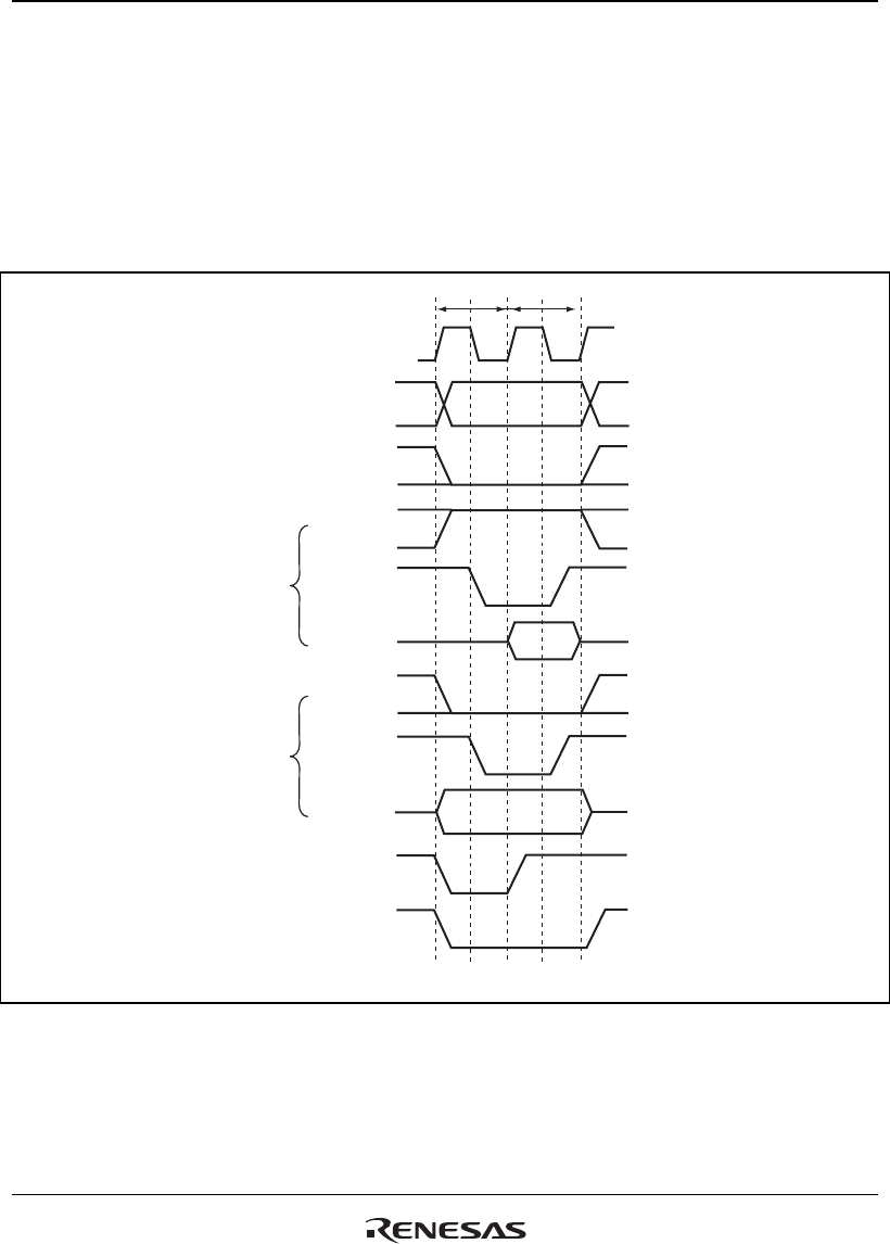
selection pin, see section 12.5.8, Byte-Selection SRAM Interface. Figure 12.3 shows the basic
timings of normal space access. A no-wait normal access is completed in two cycles. The BS
signal is asserted for one cycle to indicate the start of a bus cycle.
CKIO
Note: * The waveform for DACKn is when active low is specified.
A25 to A0
RD/WR
RD/WR
D31 to D0
DACKn
CSn
T1 T2
RD
WEn
BS
D31 to D0
Read
Write
*
Figure 12.3 Normal Space Basic Access Timing (Access Wait 0)
There is no access size specification when reading. The correct access start address is output in the
least significant bit of the address, but since there is no access size specification, 32 bits are always
read in case of a 32-bit device, and 16 bits in case of a 16-bit device. When writing, only the WEn
signal for the byte to be written is asserted.


