


Section 18 Multi-Function Timer Pulse Unit (MTU)
Rev. 4.00 Sep. 14, 2005 Page 586 of 982
REJ09B0023-0400
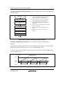
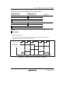
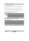
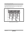
Table 18.36 Up/Down-Count Conditions in Phase Counting Mode 4
TCLKA (Channel 1)
TCLKC (Channel 2)
TCLKB (Channel 1)
TCLKD (Channel 2)
Operation
High level
Up-count
Low level
Low level Don't care
High level
High level
Down-count
Low level
High level Don't care
Low level
[Legend]
: Rising edge
: Falling edge
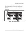
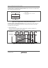
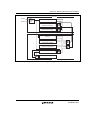
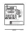
Phase Counting Mode Application Example: Figure 18.29 shows an example in which channel
1 is in phase counting mode, and channel 1 is coupled with channel 0 to input servo motor 2-phase
encoder pulses in order to detect position or speed.
Channel 1 is set to phase counting mode 1, and the encoder pulse A-phase and B-phase are input
to TCLKA and TCLKB.
Channel 0 operates with TCNT counter clearing by TGRC_0 compare match; TGRA_0 and
TGRC_0 are used for the compare match function and are set with the speed control period and
position control period. TGRB_0 is used for input capture, with TGRB_0 and TGRD_0 operating
in buffer mode. The channel 1 counter input clock is designated as the TGRB_0 input capture
source, and the pulse widths of 2-phase encoder 4-multiplication pulses are detected.
TGRA_1 and TGRB_1 for channel 1 are designated for input capture, and channel 0 TGRA_0 and
TGRC_0 compare matches are selected as the input capture source and store the up/down-counter
values for the control periods.
This procedure enables the accurate detection of position and speed.