


Section 3 DSP Operation
Rev. 4.00 Sep. 14, 2005 Page 135 of 982
REJ09B0023-0400
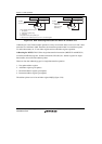
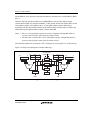
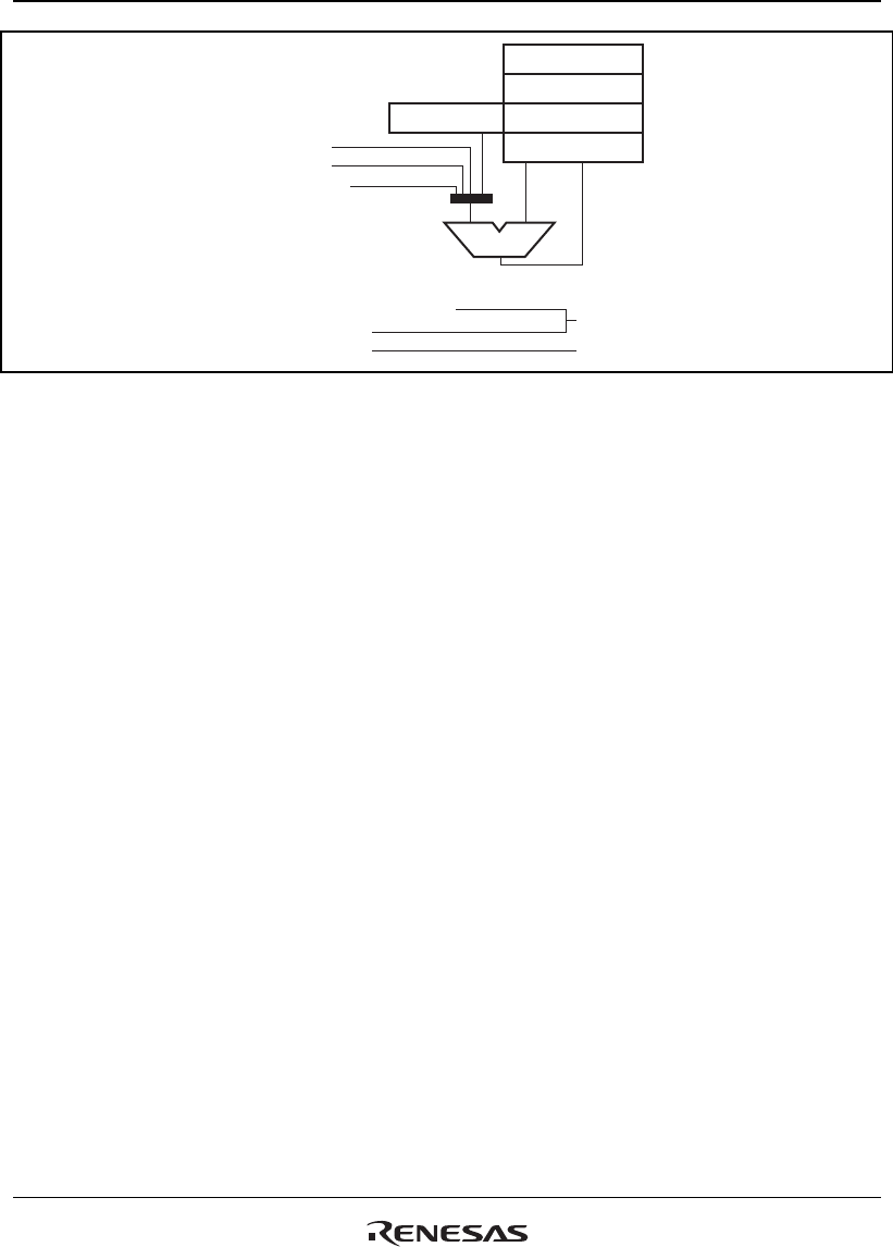
ALU
R8 [Is] R4 [As]
R5 [As]
R2 [As]
R3 [As]
–2/–4 (DEC)
+2/+4 (INC)
+0 (No update)
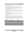
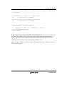
Four address operation types:
1. Not update
2. Add-index-register (Is)
3. Increment
4. Decrement
Post-update
Pre-update
Figure 3.20 DSP Addressing Instructions for MOVS
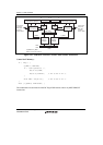
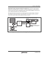
Modulo Addressing: This LSI provides modulo addressing mode, which is common in DSPs. In
modulo addressing mode, the address register is updated as explained above. When the address
pointer reaches the pre-defined address (modulo-end address), it goes to the modulo start address.
Modulo addressing is available for X and Y data transfer instructions (MOVX and MOVY), but
not for the single-data transfer instruction (MOVS). DMX and DMY in SR are used for the
modulo addressing control. If DMX is 1, the modulo addressing mode is effective for the X
memory address pointer Ax (R4 or R5). If the DMY is 1, it is effective for the Y memory address
pointer Ay (R6 or R7). Modulo addressing is available for one of X and Y address registers at one
time. A DMX = DMY = 1 case is reserved for future expansion. When both DMX and DMY are
set simultaneously, the hardware will preliminary assume that the modulo addressing mode is
effective for the Y address pointer only.
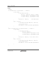
To specify the start and end addresses of the modulo address area, the MOD register, which
includes MS (modulo start) and ME (modulo end) is prepared. The following example shows a
way to set the MOD (MS and ME) register.
MOV.L ModAddr,Rn; Rn=ModEnd, ModStart
LDC Rn,MOD; ME=ModEnd, MS=ModStart
ModAddr: .DATA.W mEnd; Lower 16 bits of ModEnd
.DATA.W mStart; Lower 16 bits of ModStart
ModStart: .DATA
:
ModEnd: .DATA