Section 18 Multi-Function Timer Pulse Unit (MTU)
Rev. 4.00 Sep. 14, 2005 Page 627 of 982
REJ09B0023-0400
18.7 Usage Notes
18.7.1 Module Standby Mode Setting
MTU operation can be disabled or enabled using the module standby register.
18.7.2 Input Clock Restrictions
The input clock pulse width must be at least 1.5 states in the case of single-edge detection, and at
least 2.5 states in the case of both-edge detection. The TPU will not operate properly at narrower
pulse widths.
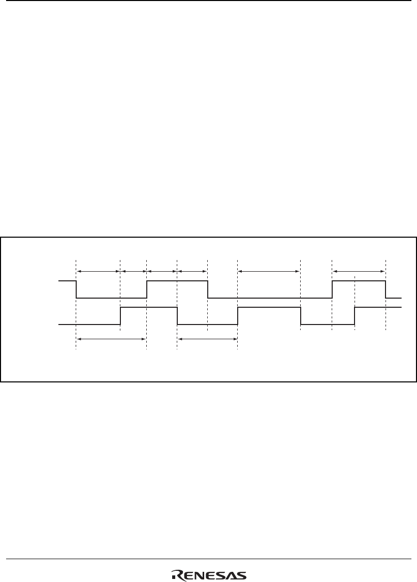
In phase counting mode, the phase difference and overlap between the two input clocks must be at
least 1.5 states, and the pulse width must be at least 2.5 states. Figure 18.70 shows the input clock
conditions in phase counting mode.
Overlap
Phase
differ-
ence
Phase
differ-
ence
Overlap
TCLKA
(TCLKC)
TCLKB
(TCLKD)
Pulse width
Pulse width
Pulse width Pulse width
Notes: Phase difference and overlap
Pulse width
: 1.5 states or more
: 2.5 states or more
Figure 18.70 Phase Difference, Overlap, and Pulse Width in Phase Counting Mode


