Section 12 Bus State Controller (BSC)
Rev. 4.00 Sep. 14, 2005 Page 369 of 982
REJ09B0023-0400
Tc1
Tr
Td1 Tde
Tap
Tr Tc1
Tnop
Trwl
Tap
(High)
CKIO
CKE
A25 to A0
CSn
RD/WR
RASL, RASU
DQMxx
D31 to D0
BS
DACKn*
2
A12/A11*
1
CASL, CASU
Notes: 1. Address pin to be connected to pin A10 of SDRAM.
2. The waveform for DACKn is when active low is specified.
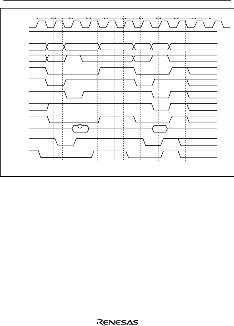
Figure 12.31 Low-Frequency Mode Access Timing
Power-Down Mode: If the PDOWN bit in the SDCR register is set to 1, the SDRAM is placed in
the power-down mode by bringing the CKE signal to the low level in the non-access cycle. This
power-down mode can effectively lower the power consumption in the non-access cycle.
However, please note that if an access occurs in the power-down mode, a cycle of overhead occurs
because a cycle is needed to assert the CKE in order to cancel the power-down mode.
Figure 12.32 shows the access timing in the power-down mode.


