


Section 6 Power-Down Modes
Rev. 4.00 Sep. 14, 2005 Page 174 of 982
REJ09B0023-0400
6.3.3 Module Standby Function
1. Transition to Module Standby Function
Setting the standby control register MSTP bits to 1 halts the supply of clocks to the
corresponding on-chip peripheral modules (however, the initial state of the USB stops). This
function can be used to reduce the power consumption in normal mode and sleep mode.
Disable a module before placing it in the module standby mode. In addition, do not access the
module's registers while it is in the module-standby state.
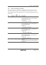
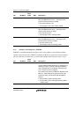
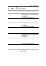
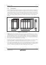
In module standby state, the functions of the external pins of the on-chip peripheral modules
change depending on the on-chip peripheral module. For details on this, see Appendix A, Pin
States. The states of the registers are the same as in the standby mode. See table 6.3.
2. Canceling Module Standby Function
The module standby function except USB can be canceled by clearing the MSTP bits to 0, or
by a power-on reset. In the case of the USB module, setting the corresponding MSTP bit to 1
cancels the module standby state. When taking a module out of the module standby state by
clearing the corresponding bit to 0 (or setting it to 1 in the case of the USB module), read the
bit to confirm that it has been cleared to 0 (or set to 1 in the USB case).
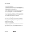
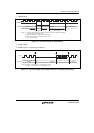
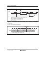
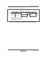
6.3.4 STATUS Pin Change Timings
To use these pins as the STATUS1 and STATUS0 pins, the corresponding setting must be made in
the PFC. For details on setting of the PFC, see section 22, Pin Function Controller (PFC). A
power-on reset initializes the PFC setting; the default value selects operation as PTC15 and
PTC14 port-input pins. Accordingly, when you wish to use these pins for the STATUS function
immediately after a power-on reset, take the following steps. This also applies to power-on resets
from the WDT and resets from the H-UDI.
1. Pull up the STATUS1 and STATUS0 pins.
2. Change the PFC setting made by power-on reset processing so that the STATUS function is
selected for these pins.
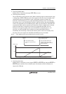
Both STATUS1 and STATUS0 become high during a power-on reset and are low on completion
of power-on reset processing. The state of the LSI is thus indicated. The timing of the level
changes of the STATUS1 and STATUS0 pins is shown below.