Section 18 Multi-Function Timer Pulse Unit (MTU)
Rev. 4.00 Sep. 14, 2005 Page 563 of 982
REJ09B0023-0400
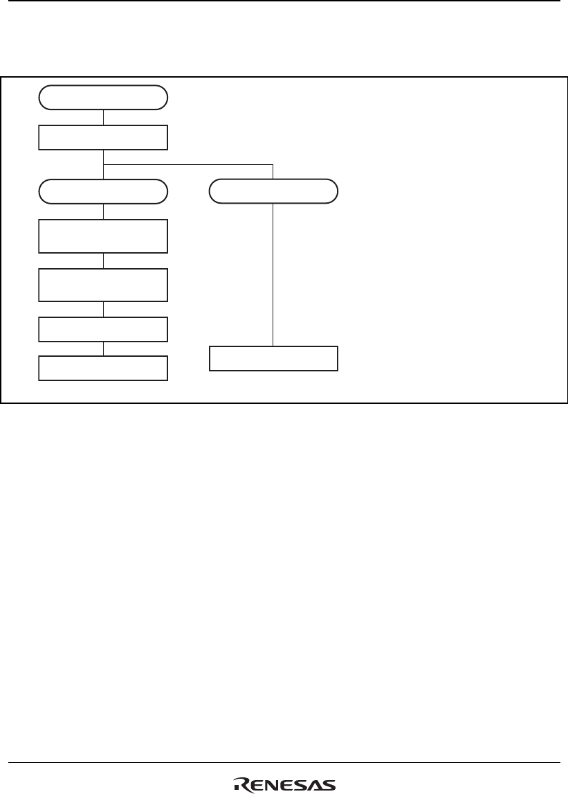
Example of Count Operation Setting Procedure: Figure 18.3 shows an example of the count
operation setting procedure.
Operation selection
Select counter clock
Periodic counter
Select counter clearing
source
Select output compare
register
Set period
Free-running counter
Start count operation
<Free-running counter>
<Periodic counter>
Start count operation
[1]
[2]
[3]
[4]
[5]
[5]
[1] Select the counter clock with
bits TPSC2 to TPSC0 in TCR.
At the same time, select the
input clock edge with bits
CKEG1 and CKEG0 in TCR.
[2] For periodic counter operation,
select the TGR to be used as
the TCNT clearing source with
bits CCLR2 to CCLR0 in TCR.
[3] Designate the TGR selected in
[2] as an output compare
register by means of TIOR.
[4] Set the periodic counter cycle
in the TGR selected in [2].
[5] Set the CST bit in TSTR to 1 to
start the counter operation.
Figure 18.3 Example of Counter Operation Setting Procedure
Free-Running Count Operation and Periodic Count Operation: Immediately after a reset, the
MTU's TCNT counters are all designated as free-running counters. When the relevant bit in TSTR
is set to 1 the corresponding TCNT counter starts up-count operation as a free-running counter.
When TCNT overflows (from H'FFFF to H'0000), the TCFV bit in TSR is set to 1. If the value of
the corresponding TCIEV bit in TIER is 1 at this point, the MTU requests an interrupt. After
overflow, TCNT starts counting up again from H'0000.
Figure 18.4 illustrates free-running counter operation.


