Section 18 Multi-Function Timer Pulse Unit (MTU)
Rev. 4.00 Sep. 14, 2005 Page 636 of 982
REJ09B0023-0400
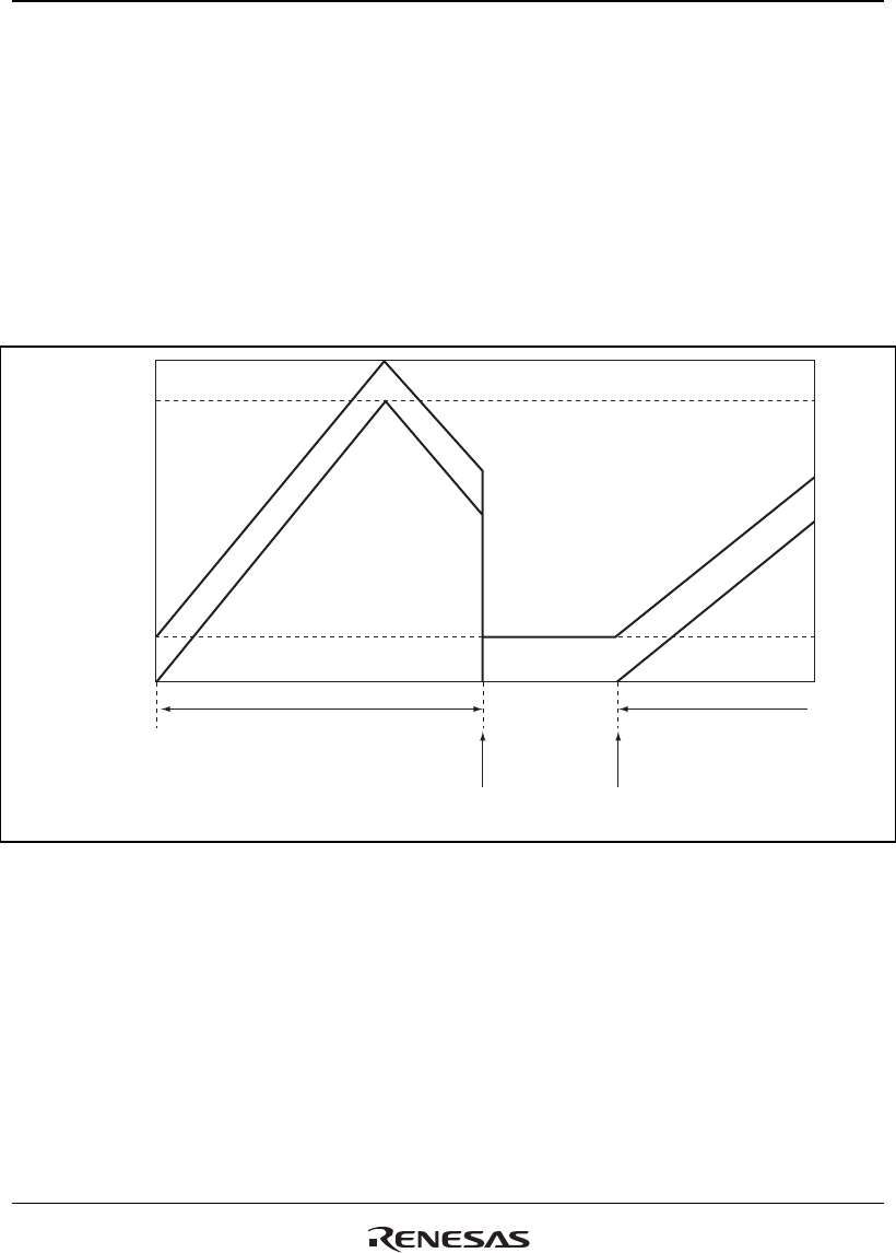
18.7.12 Counter Value during Complementary PWM Mode Stop
When counting operation is stopped with TCNT_3 and TCNT_4 in complementary PWM mode,
TCNT_3 has the timer dead time register (TDDR) value, and TCNT_4 is set to H'0000.
When restarting complementary PWM mode, counting begins automatically from the initialized
state. This explanatory diagram is shown in figure 18.80.
When counting begins in another operating mode, be sure that TCNT_3 and TCNT_4 are set to
the initial values.
TGRA_3
TCDR
TDDR
H'0000
TCNT_3
TCNT_4
Complementary PWM
mode operation
Complementary PWM
mode operation
Counter
operation stop
Complementary
PMW restart
Figure 18.80 Counter Value during Complementary PWM Mode Stop
18.7.13 Buffer Operation Setting in Complementary PWM Mode
In complementary PWM mode, conduct rewrites by buffer operation for the PWM cycle setting
register (TGRA_3), timer cycle data register (TCDR), and duty setting registers (TGRB_3,
TRGA_4, and TGRB_4).
In complementary PWM mode, channel 3 and channel 4 buffers operate in accordance with bit
settings BFA and BFB of TMDR_3. When TMDR_3's BFA bit is set to 1, TGRC_3 functions as a


