


Section 3 DSP Operation
Rev. 4.00 Sep. 14, 2005 Page 128 of 982
REJ09B0023-0400
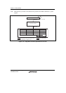
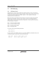
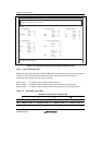
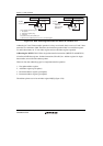
Start(End):
instr – 1
instr0
instr1
instr2
; A
; B
; C
; A
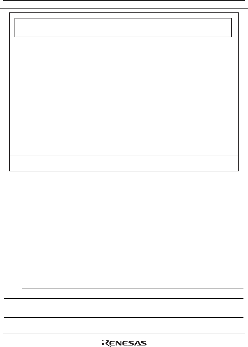
1. 1 repeated step
A: Acceptable for any interrupts
B and C: Acceptable for some interrupts
RC = 0 :
Acceptable for any interrupts
RC > 1 :
_
2. 2 repeated steps
4. 4 repeated steps 5. 5 or more repeated steps
3. 3 repeated steps
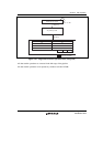
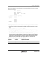
Start:
End:
instr – 1
instr0
instr1
instr2
instr3
instr4
instr4
; A
; A
; B
; C
; C
; C
; A
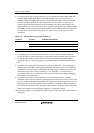
Start:
End:
instr – 1
instr0
instr1
:
:
instr n – 3
instr n – 2
instr n – 1
instr n
instr n + 1
; A
; A
; A
; B
; C
; C
; C
; A
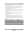
Start:
End:
instr – 1
instr0
instr1
instr2
instr3
; A
; B
; C
; C
; A
Start:
End:
instr – 1
instr0
instr1
instr2
instr3
instr4
; A
; B
; C
; C
; C
; A
Figure 3.18 Restriction of Interrupt Acceptance in Repeat Loop
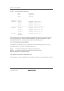
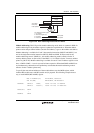
Note 1: Actual Implementation
Repeat start and repeat end registers, RS and RE, specify the repeat start instruction and repeat end
instruction. The actual addresses that are kept in these registers depend on the number of
instructions in the repeat loop. The rule is as follows:
Repeat_Start: An address of the instruction at the repeat top
Repeat_Start0: An address of the instruction before one instruction at the repeat top
Repeat_End3: An address of the instruction before three instructions at the repeat bottom
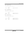
Table 3.17 RS and RE Setting Rule
Number of Instructions in Repeat Loop
1 2 3 ≥4
RS Repeat_start0 + 8 Repeat_start0 + 6 Repeat_start0 + 4 Repeat_start
RE Repeat_start0 + 4 Repeat_start0 + 4 Repeat_start0 + 4 Repeat_End3 + 4