Section 25 Electrical Characteristics
Rev. 4.00 Sep. 14, 2005 Page 964 of 982
REJ09B0023-0400
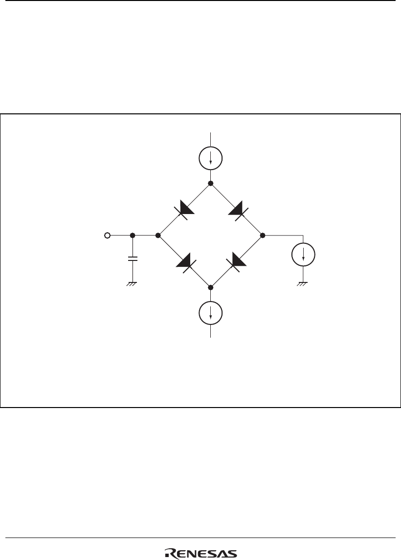
25.3.15 AC Characteristics Measurement Conditions
• I/O signal reference level: V
CC
Q/2 (V
CC
Q = 3.0 to 3.6 V, V
CC
= 1.8 V ± 5%)
• Input pulse level: V
SS
Q to 3.0 V (where RESETP, RESETM, ASEMD0, NMI, TRST, EXTAL,
CKIO, TCK, MD0, MD2, MD3, and Schmitt inputs are within V
SS
Q to V
CC
Q)
• Input rising and falling times: 1 ns
I
OL
I
OH
C
L
V
REF
LSI output pin
DUT output
Notes:
C
L
is the total value that includes the capacitance of measurement
tools. Each pin is set as follows:
30pF: CKIO, RASU/L, CASU/L, CS0, CS2 to CS6B, and BACK
50pF: All other pins
I
OL
and
I
OH
are shown in table 25.4.
1.
2.
Figure 25.56 Output Load Circuit


