Section 2 CPU
Rev. 4.00 Sep. 14, 2005 Page 27 of 982
REJ09B0023-0400
31
R0_BANK1*
1
,
*
2
R1_BANK1*
2
R2_BANK1*
2
R3_BANK1*
2
R4_BANK1*
2
R5_BANK1*
2
R6_BANK1*
2
R7_BANK1*
2
R0_BANK0*
1
,
*
3
R1_BANK0*
3
R2_BANK0*
3
R3_BANK0*
3
R4_BANK0*
3
R5_BANK0*
3
R6_BANK0*
3
R7_BANK0*
3
R8
R9
R10
R11
R12
R13
R14
R15
SR
SSR
GBR
MACH
MACL
VBR
PR
PC
SPC
031
R0_BANK0*
1
,
*
3
R1_BANK0*
3
R2_BANK0*
3
R3_BANK0*
3
R4_BANK0*
3
R5_BANK0*
3
R6_BANK0*
3
R7_BANK0*
3
R0_BANK1*
1
,
*
2
R1_BANK1*
2
R2_BANK1*
2
R3_BANK1*
2
R4_BANK1*
2
R5_BANK1*
2
R6_BANK1*
2
R7_BANK1*
2
R8
R9
R10
R11
R12
R13
R14
R15
SR
SSR
GBR
MACH
MACL
VBR
PR
PC
SPC
0
Notes: 1. The R0 register is used as an index register in indexed register indirect addressing mode
and indexed GBR indirect addressing mode.
2. Bank register
Accessed as a general register when the RB bit is set to 1 in the SR register.
Accessed only by LDC/STC instructions when the RB bit is cleared to 0.
3. Bank register
Accessed as a general register when the RB bit is cleared to 0 in the SR register.
Accessed only by LDC/STC instructions when the RB bit is set to 1.
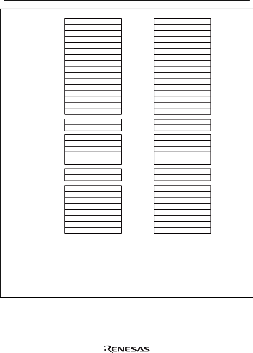
(a) Register configuration for DSP
mode and non_DSP mode (RB = 1)
(b) Register configuration for DSP
mode and non_DSP mode (RB = 0)
Figure 2.1 Register Configuration in Each Processing Mode (1)


