


Section 16 I
2
C Bus Interface 2 (IIC2)
Rev. 4.00 Sep. 14, 2005 Page 496 of 982
REJ09B0023-0400
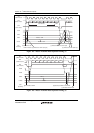
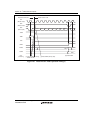
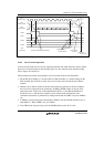
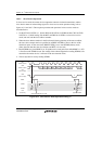
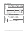
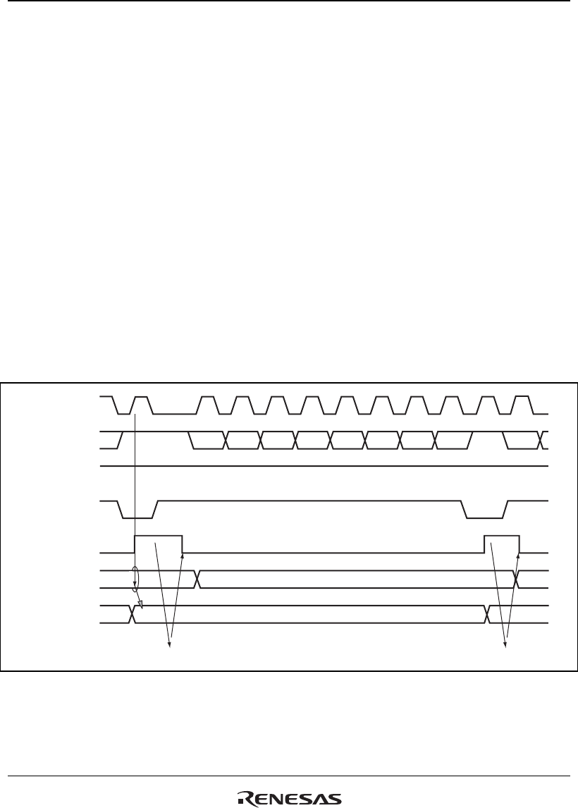
16.4.5 Slave Receive Operation
In slave receive mode, the master device outputs the transmit clock and transmit data, and the
slave device returns an acknowledge signal. For slave receive mode operation timing, refer to
figures 16.11 and 16.12. The reception procedure and operations in slave receive mode are
described below.
1. Set the ICE bit in ICCR1 to 1. Set the MLS and WAIT bits in ICMR and bits CKS3 to CKS0
in ICCR1 to 1. (Initial setting) Set the MST and TRS bits in ICCR1 to select slave receive
mode, and wait until the slave address matches.
2. When the slave address matches in the first frame following detection of the start condition,
the slave device outputs the level specified by ACKBT in ICIER to SDA, at the rise of the
ninth clock pulse. At the same time, RDRF in ICSR is set to read ICDRR (dummy read).
(Since the read data show the slave address and R/W, it is not used.)
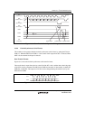
3. Read ICDRR every time RDRF is set. If eighth receive clock pulse falls while RDRF is 1, SCL
is fixed low until ICDRR is read. The change of the acknowledge before reading ICDRR, to be
returned to the master device, is reflected to the next transmit frame.
4. The last byte data is read by reading ICDRR.
ICDRS
ICDRR
12 1345678 99
AA
RDRF
Data 1 Data 2
Data 1
SCL
(Master output)
SDA
(Master output)
SDA
(Slave output)
SCL
(Slave output)
Bit 7 Bit 7Bit 6 Bit 5 Bit 4 Bit 3 Bit 2 Bit 1 Bit 0
[2] Read ICDRR (dummy read)
[2] Read ICDRR
User
processing
Figure 16.11 Slave Receive Mode Operation Timing (1)