


Section 12 Bus State Controller (BSC)
Rev. 4.00 Sep. 14, 2005 Page 315 of 982
REJ09B0023-0400
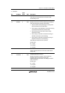
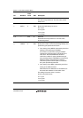
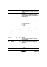
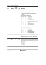
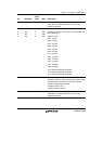
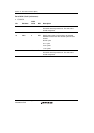
Bit Bit Name
Initial
Value R/W Description
13 DEEP 0 R/W Deep Power-Down Mode
This bit is valid for low-power SDRAM. If the RFSH or
RMODE bit is set to 1 while this bit is set to 1, the deep
power-down entry command is issued and the low-
power SDRAM enters the deep power-down mode.
0: Self-refresh mode
1: Deep power-down mode
12 SLOW 0 R/W Low-Frequency Mode
Specifies the output timing of command, address, and
write data for SDRAM and the latch timing of read data
from SDRAM. Setting this bit makes the hold time for
command, address, write and read data extended for
half cycle (output or read at the falling edge of CKIO).
This mode is suitable for SDRAM with low-frequency
clock.
0: Command, address, and write data for SDRAM is
output at the rising edge of CKIO. Read data from
SDRAM is latched at the rising edge of CKIO.
1: Command, address, and write data for SDRAM is
output at the falling edge of CKIO. Read data from
SDRAM is latched at the falling edge of CKIO.
11 RFSH 0 R/W Refresh Control
Specifies whether or not the refresh operation of the
SDRAM is performed.
0: No refresh
1: Refresh
10 RMODE 0 R/W Refresh Control
Specifies whether to perform auto-refresh or self-
refresh when the RFSH bit is 1. When the RFSH bit is
1 and this bit is 1, self-refresh starts immediately.
When the RFSH bit is 1 and this bit is 0, auto-refresh
starts according to the contents that are set in registers
RTCSR, RTCNT, and RTCOR.
0: Auto-refresh is performed
1: Self-refresh is performed