Section 20 USB Function Module
Rev. 4.00 Sep. 14, 2005 Page 791 of 982
REJ09B0023-0400
Normal routine USIHP interrupt routine
Power On Reset
Set STBCR4/MSTP46 to 1
(exit USB module stop mode)
Set USBIER2/SETC to 1
(Configuration set interrupt)
Clear USBIER2/SETC
Clear USBIFR2/SETC
Confirm USBIFR2/CFGV=1
(confirm that a trasition to
high-power function is made)
Set IPRC/IRQ0 of INTC to 15
(set the priority of IRQ0 to 15)
Set IPRC/IRQ1 of INTC to 14
(set the priority of IRQ1 to 14)
Clear ICR1/IRQ00S and
IRQ01S of INTC to 0
(set the IRQ0 falling edge
detection)
Clear ICR1/IRQ10S and
IRQ11S of INTC to 0
(set the IRQ1 falling edge
detection)
Clear ICR1/IRQE of INTC to 0
(IRQ interrupt enable)
Set USBCTRL/SUSPEND to 1
(suspend interrupt enable)
Set USBCTRL/PWMD to 1
(set to bus power control method)
USIHP interrupt?
No
Yes
Normal operation
RTE instruction
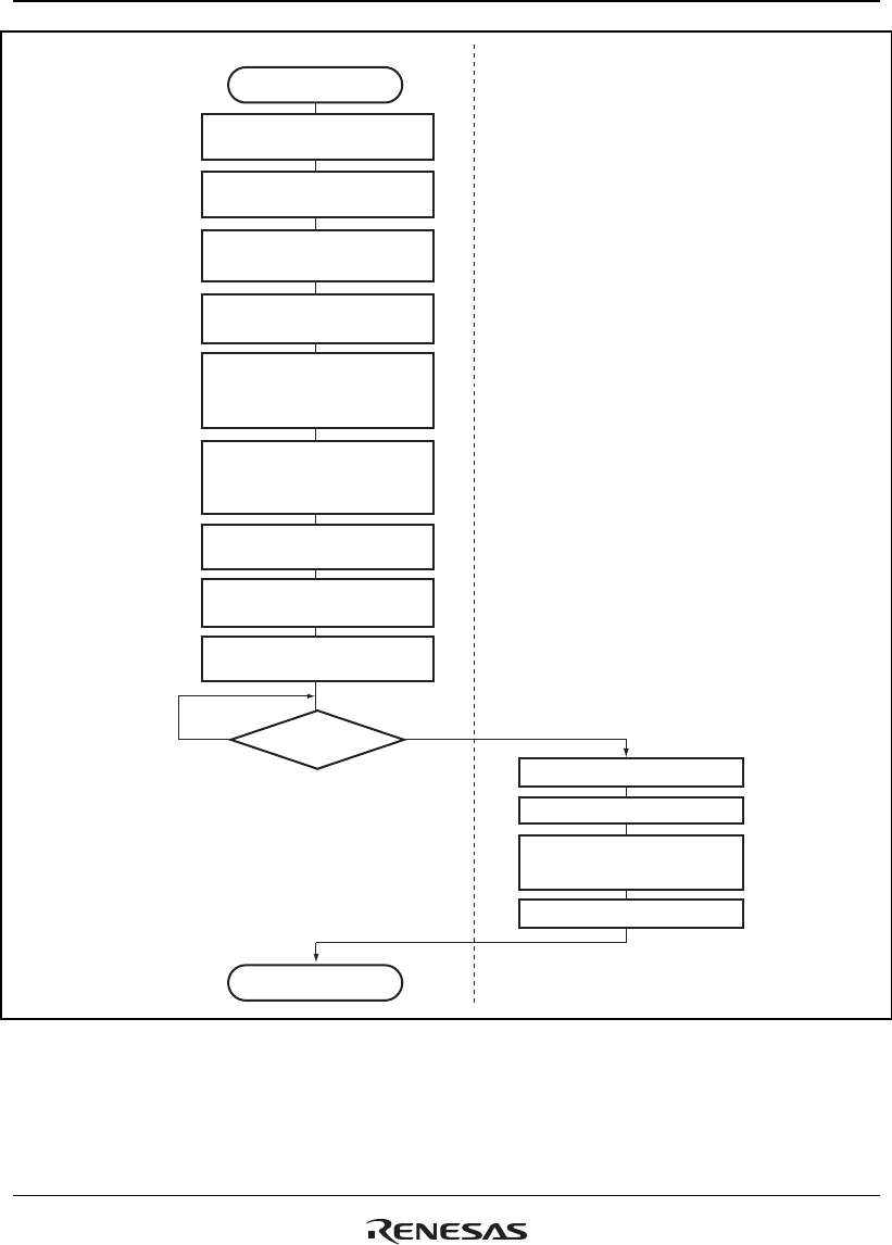
Figure 20.21 Sample Flowchart for Initialization of the USB Bus Power Control Method


