Section 18 Multi-Function Timer Pulse Unit (MTU)
Rev. 4.00 Sep. 14, 2005 Page 577 of 982
REJ09B0023-0400
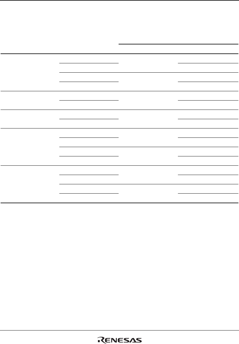
The correspondence between PWM output pins and registers is shown in table 18.31.
Table 18.31 PWM Output Registers and Output Pins
Output Pins
Channel Registers PWM Mode 1 PWM Mode 2
TGRA_0 TIOC0A
TGRB_0
TIOC0A
TIOC0B
TGRC_0 TIOC0C
0
TGRD_0
TIOC0C
TIOC0D
TGRA_1 TIOC1A 1
TGRB_1
TIOC1A
TIOC1B
TGRA_2 TIOC2A 2
TGRB_2
TIOC2A
TIOC2B
TGRA_3 Setting prohibited
TGRB_3
TIOC3A
Setting prohibited
TGRC_3 Setting prohibited
3
TGRD_3
TIOC3C
Setting prohibited
TGRA_4 Setting prohibited
TGRB_4
TIOC4A
Setting prohibited
TGRC_4 Setting prohibited
4
TGRD_4
TIOC4C
Setting prohibited
Note: In PWM mode 2, PWM output is not possible for the TGR register in which the period is set.


