


Section 2 CPU
Rev. 4.00 Sep. 14, 2005 Page 70 of 982
REJ09B0023-0400
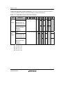
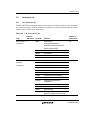
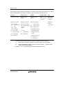
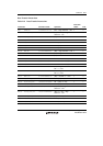
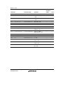
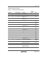
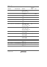
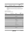
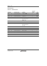
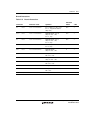
The instruction code, operation, and number of execution states of the CPU instructions are shown
in the following tables, classified by instruction type, using the format shown below.
Instruction Instruction Code Operation Execution States T Bit
Indicated by mnemonic.
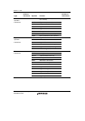
Explanation of Symbols
OP.Sz SRC, DEST
OP: Operation code
Sz: Size
SRC: Source
DEST: Destination
Rm: Source register
Rn: Destination register
imm: Immediate data
disp: Displacement
Indicated in MSB ↔
LSB order.
Explanation of Symbols
mmmm: Source register
nnnn: Destination register
0000: R0
0001: R1
.........
1111: R15
iiii: Immediate data
dddd: Displacement*
2
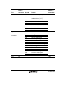
Indicates summary of
operation.
Explanation of Symbols
→, ←: Transfer direction
(xx): Memory operand
M/Q/T: Flag bits in SR
&: Logical AND of each bit
|: Logical OR of each bit
^: Exclusive logical OR of
each bit
~: Logical NOT of each bit
<<n: n-bit left shift
>>n: n-bit right shift
Value
when no wait states
are inserted*
1
Value of T bit
after instruction
is executed
Explanation of
Symbols
—: No change
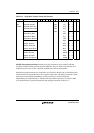
Notes: 1. The table shows the minimum number of execution states. In practice, the number of
instruction execution states will be increased in cases such as the following:
(1) When there is contention between an instruction fetch and a data access
(2) When the destination register of a load instruction (memory → register) is also
used by the following instruction
2. Scaled (×1, ×2, or ×4) according to the instruction operand size, etc.