


Section 12 Bus State Controller (BSC)
Rev. 4.00 Sep. 14, 2005 Page 281 of 982
REJ09B0023-0400
Bit Bit Name
Initial
Value R/W Description
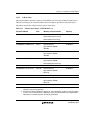
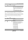
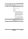
0 HIZCNT 0 R/W High-Z Control
Specifies the state in software standby mode and bus
released for CKIO2, RASU, RASL, CASU, and CASL.
0: High impedance in software standby mode and bus
released for CKIO2, RASU, RASL, CASU, and
CASL.
1: Driven in standby mode and bus released for
CKIO2, RASU, RASL, CASU, and CASL.
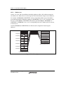
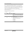
12.4.2 CSn Space Bus Control Register (CSnBCR) (n = 0, 2, 3, 4, 5A, 5B, 6A, 6B)
CSnBCR is a 32-bit readable/writable register that specifies the function of each area, the number
of idle cycles between bus cycles, and the bus-width. This register is initialized to H'36DB0600 by
a power-on reset, and it is not initialized by a manual reset and in the standby mode.
Do not access external memory other than area 0 until CSnBCR register initialization is
completed.
Bit Bit Name
Initial
Value
R/W Description
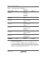
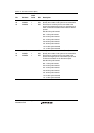
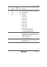
31 0 R Reserved
This bit is always read as 0. The write value should
always be 0.
30
29
28
IWW2
IWW1
IWW0
1
1
1
R/W
R/W
R/W
Idle Cycles between Write-Read Cycles and Write-
Write Cycles
These bits specify the number of idle cycles to be
inserted after the access to a memory that is
connected to the space. The target access cycles are
the write-read cycle and write-write cycle.
000: No idle cycle inserted
001: 1 idle cycle inserted
010: 2 idle cycles inserted
011: 4 idle cycles inserted
100: 6 idle cycles inserted
101: 8 idle cycles inserted
110: 10 idle cycles inserted
111: 12 idle cycles inserted