Section 10 Interrupt Controller (INTC)
Rev. 4.00 Sep. 14, 2005 Page 220 of 982
REJ09B0023-0400
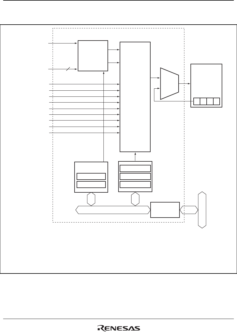
Figure 10.1 shows a block diagram of the INTC.
DMAC
SCIF0 to 2
ADC
USB
CMT0 and CMT1
MTU0 to MTU4
WDT
H-UDI
IIC2
8
DMAC:
SCIF:
ADC:
USB:
CMT:
MTU:
WDT:
H-UDI:
DMA controller
Serial communication interfaces (with FIFO) 0 to 2
A/D converter
USB funciton module
Compare match timers 0 and 1
Multifuncton timer pulse units 0 to 4
Watchdog timer
User debugging interface
IIC2:
ICR:
IPR:
IMR:
IMCR:
IRR0:
SR:
I
2
C interface 2
Interrupt control register
Interrupt priority registers B to J
Interrupt mask registers 0 to 10
Interrupt mask clear registers 0 to 10
Interrupt request register 0
Status register
I/O
controller
Priority
identifier
Com-
parator
Interrupt
request
SR
CPU
Bus
interface
Internal bus
Interrupt contoroller
I3 I2 I1 I0
(Interrupt request)
(Interrupt request)
(Interrupt request)
(Interrupt request)
(Interrupt request)
(Interrupt request)
(Interrupt request)
(Interrupt request)
(Interrupt request)
ICR
IRR0
[Legend]
IRQ7 to IRQ0
NMI
IPR
IMR
IMCR
Figure 10.1 Block Diagram of INTC


