


Section 12 Bus State Controller (BSC)
Rev. 4.00 Sep. 14, 2005 Page 316 of 982
REJ09B0023-0400
Bit Bit Name
Initial
Value R/W Description
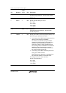
9 PDOWN 0 R Power-Down Mode
Specifies whether the SDRAM will enter the power-
down mode or not after the access to the external
memory other than the SDRAM or to the internal I/O
resister. With this bit being set to 1, the access to the
external memory other than the SDRAM or to the
internal I/O register drives the CKE signal low and
causes the SDRAM to enter the power-down mode.
0: The SDRAM does not enter the power-down mode.
1: The SDRAM enters the power-down mode after the
access to the external memory other than the
SDRAM or to the internal I/O resister.
8 BACTV 0 R/W Bank Active Mode
Specifies to access whether in auto-precharge mode
(using READA and WRITA commands) or in bank
active mode (using READ and WRIT commands).
0: Auto-precharge mode (using READA and WRITA
commands)
1: Bank active mode (using READ and WRIT
commands)
Note: Bank active mode can be used only when
either the upper or lower bits of the CS3 space
are used. When both the CS2 and CS3 spaces
are set to SDRAM, specify the auto-precharge
mode.
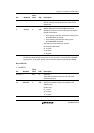
7 to 5 All 0 R Reserved
These bits are always read as 0. The write value
should always be 0.
4
3
A3ROW1
A3ROW0
0
0
R/W
R/W
Number of Bits of Row Address for Area 3
Specify the number of bits of the row address for
area 3.
00: 11 bits
01: 12 bits
10: 13 bits
11: Reserved (Setting prohibited)