


Section 13 Direct Memory Access Controller (DMAC)
Rev. 4.00 Sep. 14, 2005 Page 417 of 982
REJ09B0023-0400
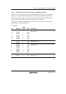
Bit Bit Name
Initial
Value R/W Description
25
24
PR1
PR0
0
0
R/W
R/W
Priority Mode 1, 0
PR1 and PR0 select the priority level between
channels when there are transfer requests for multiple
channels simultaneously.
00: Fixed mode 1: CH0 > CH1 > CH2 > CH3
01: Fixed mode 2: CH0 > CH2 > CH3 > CH1
10: The status of the channel select round-robin mode:
RCn bit is reflected to the priority.
11: All channel round-robin mode
23 to 19 All 0 R Reserved
These bits are always read as 0. The write value
should always be 0.
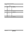
18 AE 0 R/(W)* Address Error Flag
AE indicates that an address error occurred during
DMA transfer. If this bit is set during data transfer,
transfers on all channels are suspended. The CPU
cannot write 1 to this bit. This bit can only be cleared
by writing 0 after reading 1.
0: No DMAC address error
1: DMAC address error
[Clear condition]
Writing AE = 0 after AE = 1 read
17 NMIF 0 R/(W)* NMI Flag
NMIF indicates that a NMI interrupt occurred. This bit
is set regardless of whether DMAC is in operating or
halt state. The CPU cannot write 1 to this bit. Only 0
can be written to clear this bit after 1 is read.
When the NMI is input, the DMA transfer in progress
can be done in one transfer unit. When the DMAC is
not in operational, the NMIF bit is set to 1 even if the
NMI interrupt was input.
0: No NMI input
1: NMI interrupt occurs
[Clearing condition]
Writing NMIF = 0 after NMIF = 1 read