


Section 21 A/D Converter
Rev. 4.00 Sep. 14, 2005 Page 809 of 982
REJ09B0023-0400
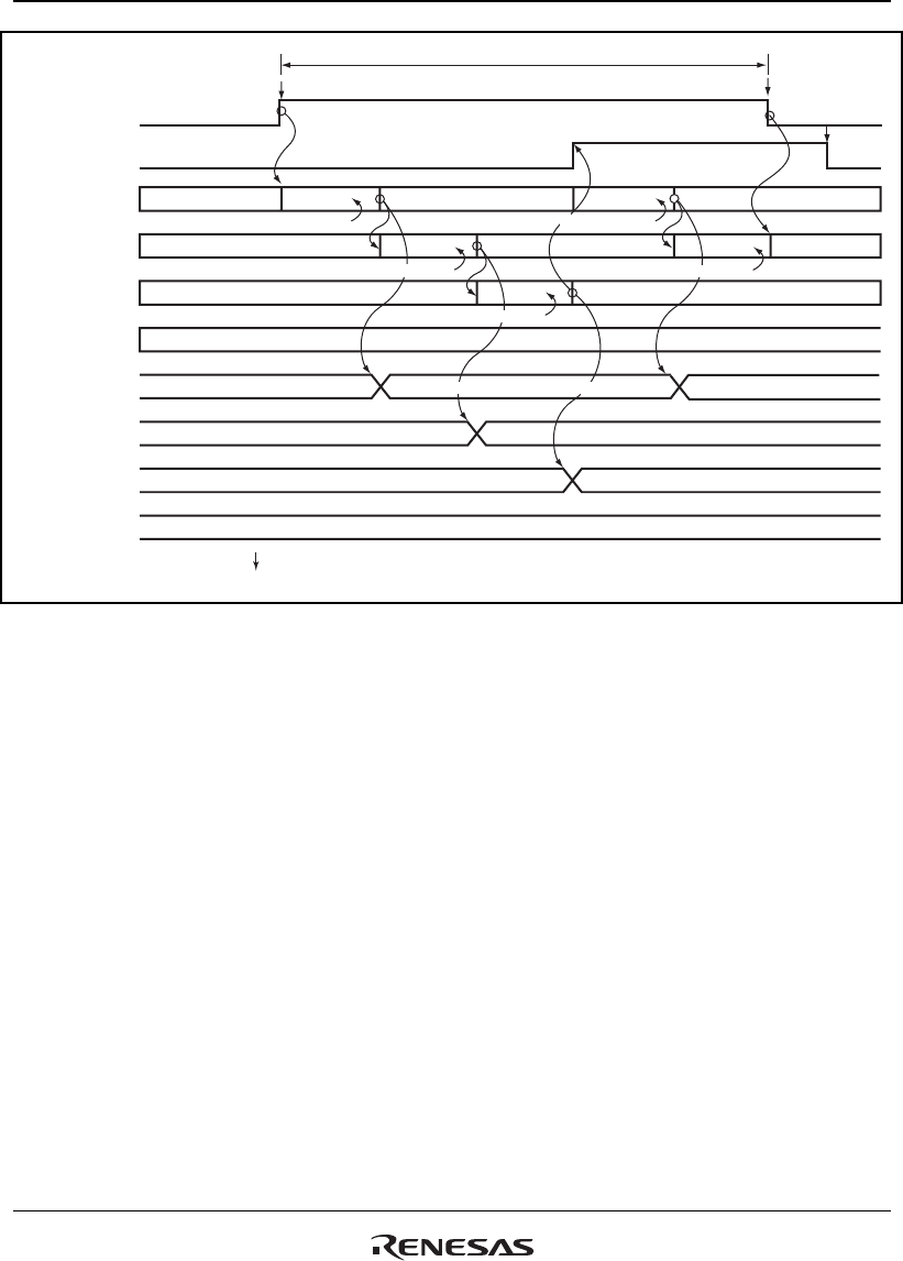
ADST
ADF
Channel 0 (AN0)
operating
Channel 1 (AN1)
operating
Channel 2 (AN2)
operating
Channel 3 (AN3)
operating
ADDRA0
ADDRB0
ADDRC0
ADDRD0
Waiting Waiting
Waiting
Waiting
Waiting
Waiting
Waiting
Waiting
Waiting
Transfer
A/D conversion 1 A/D conversion 4
A/D conversion 2
A/D conversion 3
A/D conversion result 1 A/D conversion result 4
A/D conversion result 2
A/D conversion result 3
Clear*
1
Clear*
1
Set*
1
Continuous A/D conversion
A/D conversion 5
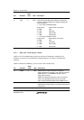
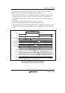
Notes: 1. Vertical arrows ( ) indicate instruction execution by software.
2. A/D conversion data is invalid/
*
2
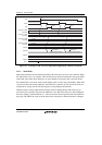
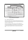
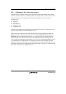
Figure 21.4 Example of A/D Converter Operation
(Scan Mode, Channels AN0 to AN2 Selected)
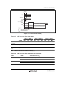
21.3.4 Simultaneous Sampling Operation
With simultaneous sampling, conversion is conducted with sampling of the input voltages on two
channels (channel in A/D0 and channel in A/D1) at the same time. Simultaneous sampling is valid
in single mode and multi mode and scan mode. Channels for sampling are determined by the CH1
and CH0 bits of the ADCSR0 or ADCSR1.
Procedure for setting simultaneous sampling is shown the next. Select the ADCSR registers
(conversion mode and input channels and conversion time), and then starts simultaneous sampling
of two channels when the DSMP bit set to 1. When DSMP bit set to 1 during A/D conversion, not
to start A/D conversion again. When the ADST bit is set, A/D conversion stops. The timing
diagrams for simultaneous sampling are the same as for single mode and multi mode and scan
mode.