


Section 10 Interrupt Controller (INTC)
Rev. 4.00 Sep. 14, 2005 Page 226 of 982
REJ09B0023-0400
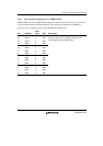
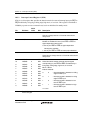
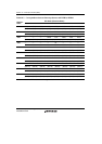
10.3.3 Interrupt Control Register 1 (ICR1)
ICR1 is a 16-bit register that specifies the detection mode for external interrupt input pins IRQ5 to
IRQ0 individually: rising edge, falling edge, high level, or low level. This register is initialized to
H'4000 by a power-on reset or manual reset, but is not initialized in standby mode.
Bit Bit Name
Initial
Value R/W Description
15 0 R Reserved
This bit is always read as 0. The write value should
always be 0.
14 IRQE* 1 R/W Interrupt Request Enable
Enables or disables the use of pins IRQ7 to IRQ0 as
eight independent interrupt pins.
0: Use of pins IRQ7 to IRQ0 as eight independent
interrupt pins enabled*
1: Use of pins IRQ7 to IRQ0 as interrupt pins disabled
13, 12 All 0 R Reserved
These bits are always read as 0. The write value should
always be 0.
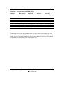
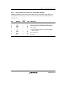
11
10
9
8
7
6
5
4
3
2
1
0
IRQ51S
IRQ50S
IRQ41S
IRQ40S
IRQ31S
IRQ30S
IRQ21S
IRQ20S
IRQ11S
IRQ10S
IRQ01S
IRQ00S
0
0
0
0
0
0
0
0
0
0
0
0
R/W
R/W
R/W
R/W
R/W
R/W
R/W
R/W
R/W
R/W
R/W
R/W
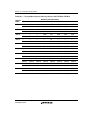
IRQn Sense Select
These bits select whether interrupt request signals
corresponding to pins IRQ5 to IRQ0 are detected by a
rising edge, falling edge, high level, or low level.
Bit 2n+1 Bit 2n
IRQn1S IRQn0S
0 0 : Interrupt request is detected on falling
edge of IRQn input
0 1 : Interrupt request is detected on rising
edge of IRQn input
1 0 : Interrupt request is detected on low
level of IRQn input
1 1 : Interrupt request is detected on high
level of IRQn input
n = 0 to 5
Note: * The IRQE bit must be cleared to 0 in the initialization routine after a reset, and must then
not be changed.