1103
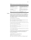
Examples # Router A and Router B are interconnected. On Router A, an IS-IS process is
created with a System ID of 0000.0000.0001 and router type of level-1-2; IS-IS is
enabled on VLAN-interface 100 with the IP address 100.1.1.1/24. On Router B,
another IS-IS process is created with a System ID of 0000.0000.0002 and router
type of level-1-2; IS-IS is enabled on VLAN-interface 100 with the IP address
100.1.1.2/24. RTA and RTB are in the same area 49.0001. Enable IS-IS adjacency
packet debugging on Router A.
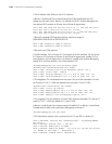
<Sysname>debugging isis adjacency
ISIS-1-ADJ: Circuit State Up Success.
ISIS-1-ADJ: Rxed Lan L1 Hello on Vlan100,from SNPA 00e0.fc00.3301.
ISIS-1-ADJ: Sending Lan L1 Hello on Vlan100.
ISIS-1-ADJ: Rxed Lan L2 Hello on Vlan100,from SNPA 00e0.fc00.3301.
ISIS-1-ADJ: Sending Lan L2 Hello on Vlan100.
ISIS-1-ADJ: Rxed Lan L1 Hello on Vlan100,from SNPA 00e0.fc00.3301.
// L2 and L2 hello packets were sent and received on VLAN-interface 100, with the
SNPA address of the peer as 00e0.fc00.3301.
ISIS-1-ADJ: Running DIS Election,Vlan100
ISIS-1-ADJ: Declaring as DIS,DIS Type L2,on Vlan100, Old DIS (null),
New DIS 0000.0000.0001.01.
ISIS-1-ADJ: Running DIS Election,Vlan100
ISIS-1-ADJ: Declaring as DIS,DIS Type L1,on Vlan100, Old DIS (null),
New DIS 0000.0000.0001.01.
// An L1/L2 neighbor relationship was established between Router A and Router B,
and a DIS election was performed.
# VLAN-interface 100 on Router A is connected to VLAN-interface 100 on Router
B. An IS-IS process is created on Router A and Router B respectively. Enable
interface circuit debugging for IS-IS. Disable IS-IS and then enable it on
VLAN-interface 100 of Router A.
<Sysname>debugging isis circuit-information
[Sysname]interface vlan-interface 100
[Sysname-Vlan-interface100]undo isis enable
[Sysname-Vlan-interface100]isis enable
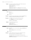
ISIS-1-CIRC: Received Circuit OperState ON : Enabling the Circuit
ISIS-1-CIRC: The IP is set to UP for IS-IS on interface Vlan100
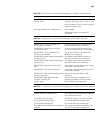
UPDT: Received LSP Not processed on P2P
Circuit due to Low Memory, Sending
Acknowledgement)
The received LSP was dropped due to
insufficient memory of the P2P interface and
an acknowledgement packet was sent.
UPDT: LSP newer than data base copy. The received LSP is newer and the local LSDB
is updated.
UPDT: Expired Own LSP received. Just
Acknowledging.
Remaintime of the received LSP is 0 and
therefore only an acknowledge packet is sent.
UPDT: LSP’s SeqNumber is 0. The LSP’s sequence number is 0, which is
invalid.
UPDT: Err, Area Addr Option in pseudonode
Lsps !!
Error: The area address TLV exists in
pseudonode LSPs.
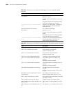
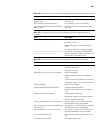
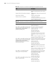
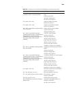
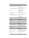
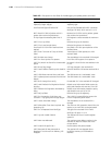
Table 261 Description on the fields of the debugging isis update-packet command
Field Description


