221
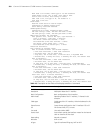
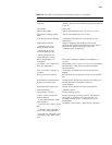
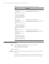
Itf number Number of interframe filling tags
Loop back Loopback setting on the interface: local, payload, remote,
or not set
Alarm State Alarm state
Receiver alarm state Type of received alarm: none, LOS, LOF, RAI, or AIS
Transmitter is sending remote
alarm.
Type of transmitted alarm: RAI, or none
Pulse density violation detected The detected pulse density is incompliant with the
specification
SendLoopCode History:
inband-llb-up:0 times,
inband-llb-down:0 times.
fdl-ansi-llb-up:0 times,
fdl-ansi-llb-down:0 times.
fdl-ansi-plb-up:0 times,
fdl-ansi-plb-down:0 times
History of loopback code sending to the far-end,
including the number of transmissions for each type of
code, and the type of the last sent code. (See
“sendloopcode” on page 229.)
BERT state:(stopped, not
completed)
BERT state: completed, stopped (not completed), or
running.
Test pattern: 2^15, Status: Not
Sync, Sync Detected: 0
Test pattern in use (2^20 or 2^15), 2^15 in this example;
synchronization state, and the number of detected
synchronizations
Time: 0 minute(s), Time past: 0
minute(s)
The duration of the BERT test and the time that has
elapsed
Bit Errors (since test started) Number of bit errors received since the start of the BERT
test
Bits Received (since test started) Number of bits received since the start of the BERT test
Bit Errors (since latest sync) Number of bit errors received since the last
synchronization
Bits Received (since latest sync) Number of bits received since last synchronization
Historical Statistics: Historical statistics
Last clearing of counters Counter clearing records
Data in current interval (285
seconds elapsed):
0 Line Code Violations, 0 Path
Code Violations
0 Ais Alarm Secs, 286 Los Alarm
Secs
7 Slip Secs, 286 Fr Loss Secs, 0
Line Err Secs, 0 Degraded Mins
0 Errored Secs, 0 Bursty Err Secs,
0 Severely Err Secs, 286 Unavail
Secs
Statistics spanning the current interval. The statistical
items, such as AIS alarm, LOS signal, and LFA, are
provided according to the T1 specifications for the
physical layer.
For details, refer to ANSI T1.403 and AT&T TR 54016.
Table 18 Description on the fields of the display controller t1 command
Field Description


