370 CHAPTER 21: BASIC DLSW CONFIGURATION COMMANDS
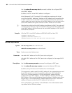
Use the undo sdlc window command to restore the default setting.
By default, the maximum number of consecutive frames the device can send
before receiving an acknowledgement from the peer is 7.
Example # Set the maximum number of consecutive frames the device can send before
receiving an acknowledgement from the peer to 5 on Serial 2/0.
<Sysname> system-view
[Sysname] interface serial 2/0
[Sysname-Serial2/0] sdlc window 5
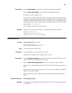
sdlc xid
Syntax sdlc xid sdlc-address xid-number
undo sdlc xid sdlc-address
View Synchronous serial interface view
Parameter sdlc-address: SDLC address corresponding to the XID to be configured, in the
range of 0x01 to 0xFE. This address should be configured beforehand.
xid-number: XID of the SDLC-enabled device, a 4-byte integer, in the range of 1 to
0xFFFFFFFF. The first 12 bits indicate the network address, and the last 20 bits
indicate the node number.
Description Use the
sdlc xid command to configure the XID of the SDLC.
Use the undo sdlc xid command to delete the XID of the SDLC.
By default, no SDLC XID is configured on a synchronous serial interface.
An XID identifies a device in an SNA system. When configuring an SDLC
connection, pay attention to the types of the connected SNA devices. Generally,
there are two types of devices in an SNA system: PU2.0 and PU2.1. An XID has
been configured on PU2.1 devices, so they can announce their identity by
exchanging the XID. A PU2.0 device does not come with an XID. Therefore, this
command is not needed on PU2.1 devices, but it is required on PU2.0 devices to
specify an XID.
Example # Set the XID of the device whose SDLC address is 0x05 to 0x2000 on Serial 2/0.
<Sysname> system-view
[Sysname] interface serial 2/0
[Sysname-Serial2/0] sdlc xid 05 2000


