


453
By default, no PVC is created. When creating such a PVC, if you do not set the
relevant attributes for the PVC, its flow control parameters will be the same as that
of the X.25 interface (the flow control parameters on an X.25 interface can be set
by the x25 packet-size and x25 window-size commands).
As one corresponding address mapping is created along with the PVC, it is
unnecessary (or impossible) to establish an address mapping first before creating
PVCs.
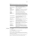
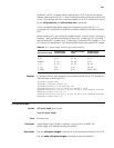
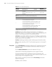
Before creating PVCs, you should first enable the PVC channel range. The range is
between 1 and the latest unprohibited channel PVC number minus 1 (including 1
and the lowest PVC number minus 1). Naturally, if the lowest PVC number is 1, the
PVC section will be disabled. The following table shows some typical PVC ranges.
Example # Configure the link layer protocol on the interface Serial 2/0 as X.25, enable PVC
channel range, and set two PVCs.
<Sysname> system-view
[Sysname] interface serial 2/0
[Sysname-Serial2/0] link-protocol x25
[Sysname-Serial2/0] x25 vc-range bi-channel 8 1024
[Sysname-Serial2/0] x25 pvc 2 ip 202.38.168.1 x121-address 20112451
broadcast packet-size 512 512
[Sysname-Serial2/0] x25 pvc 6 ip 202.38.168.3 x121-address 20112453
broadcast window-size 5 5
x25 queue-length
Syntax x25 queue-length queue-length
undo x25 queue-length
View Interface view
Parameter queue-length: Queue length in packets, ranging from 0 to 9999. The
queue-length of 0 indicates sending no packets.
Description Use the
x25 queue-length command to set the data queue length for X.25 VC.
Use the
undo x25 queue-length command to restore the default.
Table 68 PVC channel ranges for some typical configurations
PVC channel range
Incoming-only
channel range
Two-way channel
range
Outgoing-only
channel range
Disabled [0, 0] [1, 1024] [0, 0]
[1, 9] [0, 0] [10, 24] [0, 0]
Disabled [1, 10] [15, 30] [0, 0]
[1, 4] [5, 10] [15, 25] [30, 32]
[1, 19] [0, 0] [0, 0] [20, 45]
[1, 4094] [0, 0] [0, 0] [4095, 4095]