


1003
Chapter 54 Flash Memory
7.Auto Algorithms
7.3 Hardware Sequence Flag
This Flash memory performs the write/erase sequence via Auto Algorithms. It thus has hardware for informing
the outside world when it has finished internal operations.
Hardware sequence flag
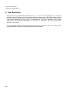
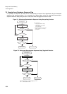
The hardware sequence flag can be obtained as data by reading any address (an odd address during byte
access) from the Flash memory while an Auto Algorithm is executing. Five of the retrieved bits of data are
valid, each indicating the status of its corresponding Auto Algorithm.
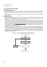
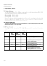
Figure 7-3 Hardware Sequence Flag Format
Note that these flags are meaningless in FR-CPU ROM mode. Read this data as a half-word or byte, and only
in FR-CPU programming mode.
• Ready/busy signal (RDY/BUSYX)
In addition to the hardware sequence flag, the Flash memory has a ready/busy signal for indicating
whether an internal Auto Algorithm is executing. This ready/busy signal can be connected to the Flash
memory interface circuit, and read as the “RDY” bit of the FLASH Memory Control Status Register.
Additionally, by starting up the ready/busy signal, it is possible to issue interrupt requests to the CPU
(See “4. Registers (Page No.996)” for more information).
Value “0” read from “RDY” bit: Flash memory is currently writing or erasing. At this time, write and
erase commands are not accepted.
Value “1” read from “RDY” bit: Flash memory is currently on standby for read/write or erase.
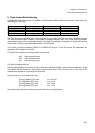
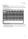
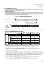
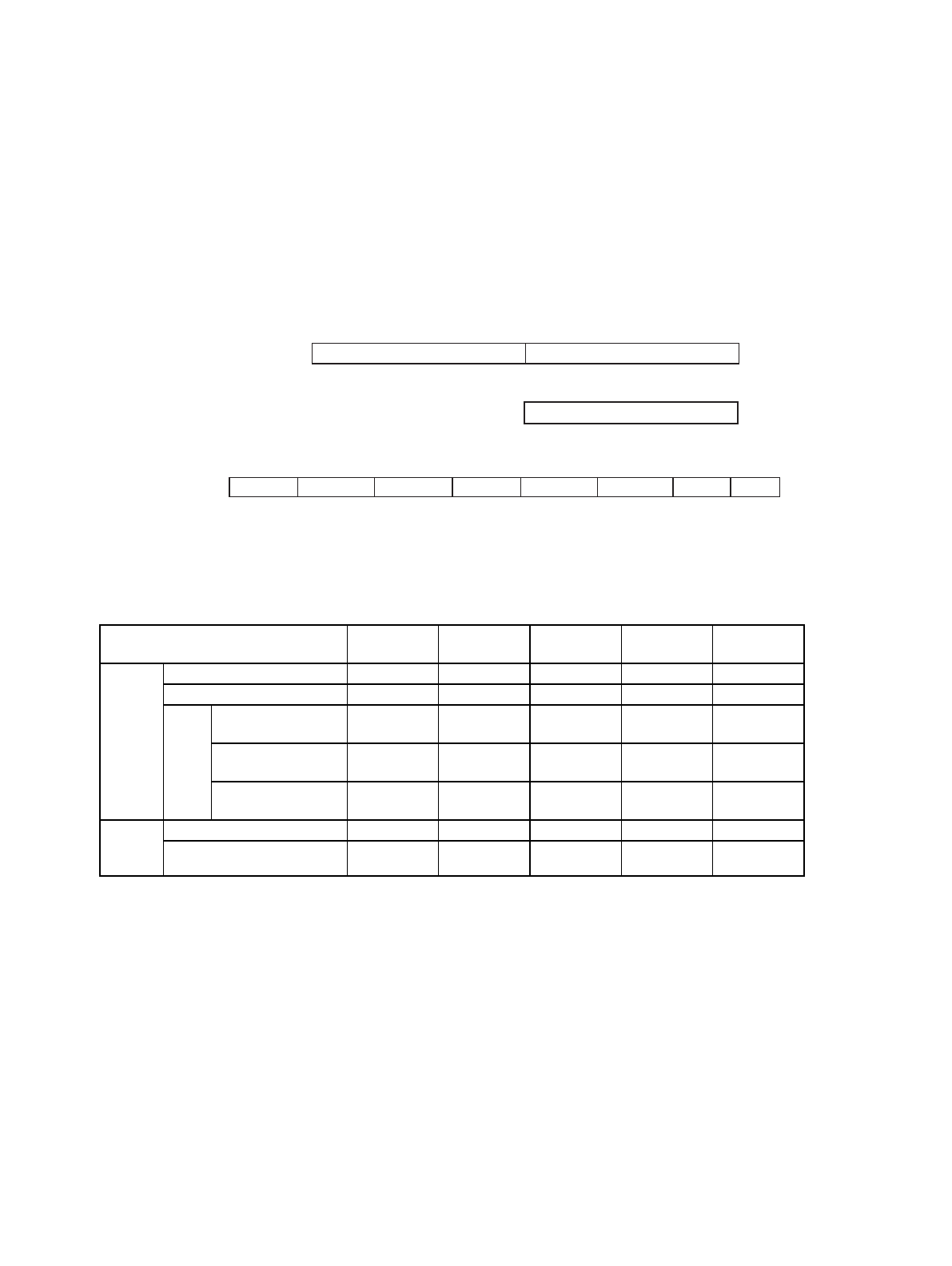
Table 7-2 List of Hardware Sequence Flag States
Status
DPOLL
(Bit 7)
TOGGLE
(Bit 6)
TLOVER
(Bit 5)
SETIMR
(Bit 3)
TOGGL2
(Bit 2)
Executing
Auto write Inverted data Toggles 0 0 1
Write/erase during auto-erase 0 Toggles 0 1 Toggles
Erase
suspended
(paused)
Read (sectors being
erased)
1 1 0 0 Toggles
Read (sectors not
being erased)
Data Data Data Data Data
Write (sectors not
being erased)
Inverted data Toggles 0 0 1 (*1)
Time
limit
exceeded
Auto write Inverted data Toggles 1 0 1
Write/erase during auto-erase 0 Toggles 1 1 (*2)
*1:During erase-suspend write mode, when an address that has been written to is read, bit 2 outputs logical
“1”.
When data is read sequentially from an erase-suspended sector, however, bit 2 is toggled.
*2:When bit 5 is set to “1” (time limit exceeded), sequential reads of sectors being written to/erased toggle
bit 2, while reads from other sectors will not toggle bit 2.
bit 15 8 7 0
When reading from hardware (Indeterminate)
Hardware sequence flag
bit 7 0
When reading from byte (Odd address only)
Hardware sequence flag
76 543 210
DPOLL TOGGLE TLOVER
(Indeterminate)
(Indeterminate)
(Indeterminate)
SETIMR
TOGGL2
bit
During
half-word
byte access