


225
Chapter 16 Clock Supervisor
4.Operation Modes
4. Operation Modes
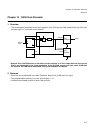
This section describes all operation modes of the Clock Supervisor.
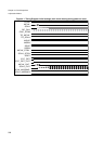
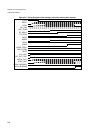
■ Operation mode with initial settings
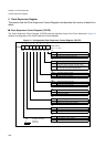
In case the clock supervisor control register (CSVCR) is not configured at the beginning of the user program, the
RC-oscillator, the main clock supervisor and the sub-clock supervisor is enabled.
• The RC-oscillator is enabled at power-on.
• The main clock supervisor is enabled after the ’oscillation stabilisation wait time’ with the rising edge of signal
OSC_STAB or in case the main clock is missing before the completion of the ’oscillation stabilisation wait
time’, after the ’main clock timeout’ (TO_MCLK) from the timeout counter. The timeout counter is clocked with
RC-oscillation clock. If the main clock is missing from power-on, the power-on reset state is never left, which in
this case is a safe state. The user must make sure with external pull-up/pull-down resistors that all relevant
signal are pulled to the correct level.
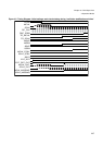
• The sub-clock supervisor is enabled after the completion of the ’sub-clock timeout’ (TO_SCLK) from the
timeout counter. The timeout counter is clocked with RC-oscillation clock.
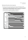
• If the main clock stops while the main clock supervisor is enabled, the main clock is replaced with the RC-
oscillation clock, the MM bit is set to ’1’ and reset (EXT_RST_OUT) is asserted.
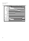
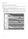
• If the sub-clock stops and the sub-clock supervisor is enabled, the behaviour depend on whether the MCU is
in main clock mode or in sub-clock mode. If the sub-clock stops in sub-clock mode, the RC-oscillation clock
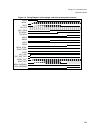
divided by two substitutes the sub-clock, the SM bit is set to ’1’ and reset (EXT_RST_OUT) is asserted. If the
sub-clock stops in main clock mode, the RC-oscillation clock divided by two substitutes the sub-clock, the SM
bit is set to ’1’ and no reset occurs upon transition to sub-clock mode, since the SRST bit has its initial value of
’0’.