


281
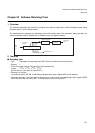
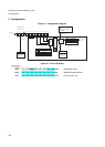
Chapter 20 Software Watchdog Timer
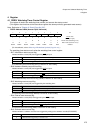
7.Q & A
7. Q & A
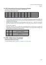
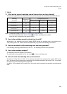
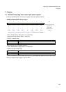
7.1 What are the types of watchdog interval time and how are they selected?
There are four types of the interval period, and they are set using the interval selection bit (RSRR.WT[1:0]).
Note: F: Base clock. (Refer to “Chapter 13 Clock Control (Page No.189)”.)
Only the data sets first written after the reset (INIT pin input, watchdog reset, software
reset) are valid, and the other data sets are invalid.
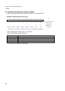
7.2 How is the watchdog operation started (set to valid)?
Writing data in the watchdog timer control register RSRR causes the watchdog timer to be started (set to
valid). Writing data in the interval selection bit (RSRR.WT[1:0]) causes the watchdog to be started.
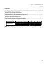
7.3 How can we check that the watchdog reset has been generated?
If the watchdog reset flag (RSRR.WDOG) is set to “1”, the watchdog reset has been generated.
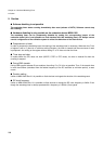
7.4 How is the watchdog stopped?
The watchdog cannot be stopped by the software.
The watchdog can be stopped only with the reset (INIT pin input, watchdog reset).
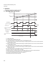
7.5 How do I clear the watchdog timer (1-bit counter)?
Successively writing “A5
H
” and “5A
H
” in the watchdog reset generation postponement register WPR causes
the 1-bit counter used for detecting the watchdog to be cleared immediately after writing “5A
H
”. In this state,
the reset timing of the watchdog can be postponed.
In addition, if the timebase timer is cleared, the 1-bit counter used for detecting the watchdog is simultaneously
reset.
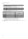
Watchdog
Interval time
Interval
Selection bit
(WT[1:0])
Example) Interval Time
FΦ =80.0MHz FΦ = 2.00MHz FΦ = 32.768kHz
To select Φ × 2
20
Set the value to
“00”
13.1 ms 0.524 s 32.0 s
To select Φ × 2
22
Set the value to
“01”
52.4 ms 2.097 s 128.0 s
To select Φ × 2
24
Set the value to
“10”
209.7 ms 8.388 s 512.0 s
To select Φ × 2
26
Set the value to
“11”
838.8 ms 33.554 s 2048.0 s