567
Chapter 31 External Bus
5.Operation of the Ordinary bus interface
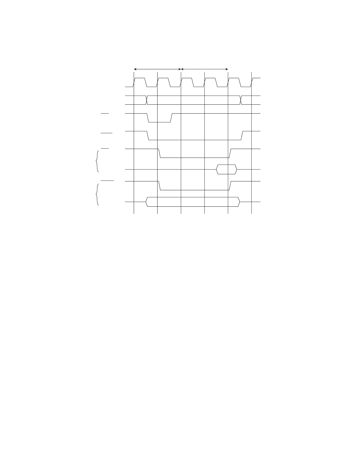
Figure 5-5 Timing Chart for the Auto-Wait Cycle
Setting of the W15-12 bits (first wait cycles) of the AWR register enables 0-15 auto-wait cycles to be set.
In Figure 5-5 "Timing Chart for the Auto-Wait Cycle", two auto-wait cycles are inserted, making a total of four
cycles for access. If auto-wait is set, the minimum number of bus cycles is 2 cycles + (first wait cycles). For a
write operation, the minimum number of bus cycles may be still longer depending on the internal state.
5.6 External Wait Cycle
This section shows the operation timing for the external wait cycle.
■ External Wait Cycle Timing
Figure 5-6 "Timing Chart for the External Wait Cycle" shows the operation timing for (TYP3-0=0001
B
,
AWR=2008
H
).
Basic cycle Wait cycle *
MCLK
A[31:0]
AS
CSn
RD
D[31:0]
WRn
D[31:0]


