254
Chapter 18 Timebase Counter
5.Operation
5.2 Watchdog Reset (The specified oscillation stabilization wait time is generated
automatically)
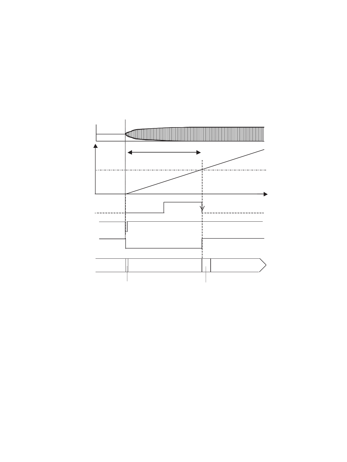
If a watchdog reset occurs while the main clock oscillation is halted, the oscillation stabilization wait time is
generated automatically. (See figure below.)
Figure 5-2 Watchdog Reset when Main Clock Halted (Sub RUN)
(1) Oscillation stabilization wait time selection (Example: Main clock divided by two x 2
22
)
(Set the interval time beforehand to provide an adequate oscillation stabilization wait time.)
(2) Sub RUN with main clock oscillation halted
(3) Watchdog reset occurs
(4) Main clock oscillation starts
The timebase counter is cleared and starts counting.
(5) Oscillation stabilization wait
(6) Time set as the timebase timer interval time (time set in (1))
(7) Reset released, operation initialization (SRST)
(8) Operation initialization, reset sequence
(9) Main RUN
Note: If a watchdog reset occurs when the main clock oscillation is halted during subclock mode (subclock is
being used as clock source) by the main clock oscillation halt bit (OSCCR.OSCDS1), the device changes
to the oscillation stabilization wait state after the settings initialization reset (INIT) is released. The device
then changes to the operation initialization reset (RST) state after the oscillation stabilization wait time
elapses.
22
2
Using the time-base counter to
provide the oscillation stabilization
wait time for the main clock
Time-base
counter
count
Example main clock startup
(7)
(6)
(4)
Watchdog
Time
000h
(2)
2
22
(Bit 21 output)
Provide a sufficient oscillation
stabilization wait time
(3)
Settings initialization
(INIT)
Operation initialization (SRST)
Reset cancellation sequence
Oscillation stabilization wait reset
Sub RUN with main clock
oscillation halted
State transition
Main RUN
(4)
(6)
Internal reset signal
(5)
(8) (9)
(1)


